 |
|
1. Vehicle Trajectory Mapping System Ver.2
2. xpswmm
3. Overseas Training and Seminars
|
1. Vehicle Trajectory Mapping System Ver.2
(supports only Japanese and Chinese version is under development) |
| In this revision, the driving styles and vehicle types have been increased and the linkage with VR-Design Studio (formally known as UC-win/Road), 3D Visual Interactive Simulation & Modeling software, has been strengthened. |
When drawing a driving route that includes even a single sharp turn such as the one seen in Figure 1 in which the driver is required to turn the steering wheel rapidly, a turning radius and all the straight lines forming the turn had to be assigned aside from assigning straight lines for other parts of the driving route. Users are no longer required to do this extra work with this new version as it is capable of drawing a driving route with sharp turns in one operation, saving users' time considerably.
 |
Figure 1 Driving route with sharp turns
(The corner in which rapid turning of
Steering wheel is required is marked in
red circle) |
|
Articulated bus is now available as a new vehicle type. An articulated bus comprises two rigid sections linked by a pivoting point as shown in Figure 2 through which passengers can pass. In this software, the trajectory of an articulated bus is calculated assuming that it behaves like a full-trailer.
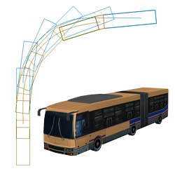 |
Figure 2
Trajectory of articulated bus |
|
Ability to assign turning radius that corresponds to speed or vice-versa
|
A feature that allows users to input and graph the relation between speed
and turning radius of a vehicle has been added. With this new feature,
users can easily find out the vehicle's turning radius that corresponds
to its speed by inputting the latter or vice-versa.
 |
Figure 3 The relation between
speed and the turning radius |
|
| Ability to adjust driving route. |
This new feature allows users to adjust lines that form a driving route. For instance, an ideal turning trajectory can be determined by checking whether the vehicle travels off the route assigned in the first place and then adjusting the route so that the vehicle does not go off route. Since the turning trajectory can be adjusted and confirmed visually as shown in Figure 4, driving route can be set easier than ever before.
 |
Figure 4
Line (route) adjustment function |
|
| Ability to assign 3D model |
When importing a vehicle model using OpenMicroSim file output function
in ver. 1, rectangular model that meets the vehicle's specification is
output so that it can be imported to UC-win/Road. If users needed to import
another type of model, they were required to do so in UC-win/Road. This
work can now be done in Vehicle Trajectory Mapping System.
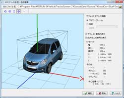 |
Figure 5 3DVR simulation
(UC-win/Road) |
|
Ability to assign stopping time
|
Vehicle's stopping time can now be assigned and saved into OpenMicroSim file. The stopping time for each point on the driving route including the start point, the point at which the vehicle starts and stops turning, and end point as shown in Figure 6 can be assigned. point at a point before the vehicle starts driving, time can be set for "Start driving position", "Start / finish turning position (quick turning position)" and "Finish driving position" as showing in. Moreover, when saving the OpenMicroSim file, stopping time can be assigned for each step of calculated trajectory.
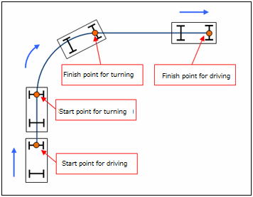 |
| Figure 6 Points at which the vehicle stops |
|
Drawing the axis of wheel on a plan
|
It is now possible to draw the axis of wheel on a plan (Figure 7). Users can choose whether to draw or not, enabling them to create a drawing in further detail.
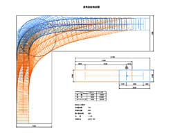 |
Figure 7 Drawing on a plan
(with axis of wheel) |
|
|
| Auto-generating a road model |
1D/2D analysis which has been developed and promoted as state-of-the-art technology of xpswmm to realize highly accurate simulation has gained its popularity in recent years. On the other hand, there are still many opportunities to analyze by a road model in the previous 1D analysis and so the both 1D and 2D analysis will be run according to users' objective for the time being. In order to construct a road model using the previous version, manual input and complicated operation was required. This labor is no longer required in the new version as road models can be automatically generated, allowing users to model very efficiently.
 |
| Figure 1 Basic concept of a road model |
These are the steps to assigning a road model. Register the road section placed between the edge stones to the global data as an assumed open channel.
 |
| Figure 2 Register the road section |
Now these are the new steps. If you select two or more links to which you
want to apply the road model and then select "Double drainage batch
conversion" from the tool menu, longitudinal values and extension
including the open channel invert are automatically assigned from the input
culvert information and an executable model is immediately constructed.
 |
 |
| Figure 3 Input the road section |
Figure 4 Auto-generating
a road model from a tool bar |
 |
 |
 |
| Figure 5 Window for activating auto-generation |
Figure 6
An auto-generated road model |
Figure 7 Output the auto-generated road model |
| Optimizing the regulation pond and discharge conduit |
An optional feature that optimizes the amount of water to be accumulated
in the regulation pond and the amount of discharge has been enhanced. It
is difficult to clearly determine the amount of water that need to be accumulated
and the minimal diameter of the pipe of discharge conduit required for
the planned rainfall as calculations need to be repeated several times
to meet the requirements. This calculation is now automated in the new
version. In order to let the system do the calculation, click the "Optimize"
button in "input accumulating node" dialogue, assign conditions
in the window that appears and then execute the analysis. The system will
then do the calculations until the requirements are met.
 |
 |
| Figure 8 Button for optimization |
Figure 9 Assigning
maximum allowable amount of discharging |
|
| 3. Overseas Seminars and Exhibition |
Exhibition
| Date |
Exhibition Name |
Location |
| 10/22-26 |
ITS World Congress |
Vienna, Austria |
| 11/20 |
FORUM8 London VR Conference |
St Paul's Cathedral |
For more information and applications, please email us at
mailto : brendan@forum8.com
Gross circulation: 6438
To subscribe this page, go to http://www.forum8.co.jp/english/p-mail-e.htm
If you would like to unsubscribe from our newsletters, please include "Unsubscribe"
in the subject title of your email and send it back to us.
Thank you for your continued support.
FORUM8 Co., Ltd. mailto:forum8@forum8.co.jp
Nakameguro GT Tower 15F
2-1-1 Kamimeguro Meguro-ku Tokyo 153-0051 JAPAN
TEL +81-3-5773-1888
FAX +81-3-5720-5688
http://www.forum8.com/ |
|


