New Products
Engineer's Studio® Ver.2.01
Applied for SFHB 2012
Dynamic nonlinear analysis for 3D multi-layer plate and cable

●Price Ultimate: US18,000/(Excluding Maekawa model): US$11,500
       (Exclusind cable element): US$15,000
       Advanced: US$7,800/Lite: US$5,200/Base: US$3,300
●Release January 22, 2013
UC-win Series Dynamic nonlinear analysis
Introduction
Engineer's Studio® Ver 2.01 now supports the following 2 items. All of them are regarding the frame element.
  1. Verification of cross section based on the limit state design method
  2. M−θmodel of NEXCO Design Scheme Chapter 2, July 2012
Verification of cross section based on the limit state design method
Mainly the ultimate limit, serviceability limit, fatigue limit, durability (corrosion), safety (destruction of cross section, fatigue) are verified. The referred criteria is as followings.
  • Concrete Standard Specifications (Design), 1996
  • Concrete Standard Specifications (Verification of structural performance), 2002
  • Concrete Standard Specifications (Design), 2007
  • Design standards for railway structure (concrete structure), 1999
  • Design standards for railway structure (concrete structure), 2004
Call the input from within a red frame of following and set the following items.

画像をクリックすると大きな画像が表示されます。
Figure 1 Input of limit state design

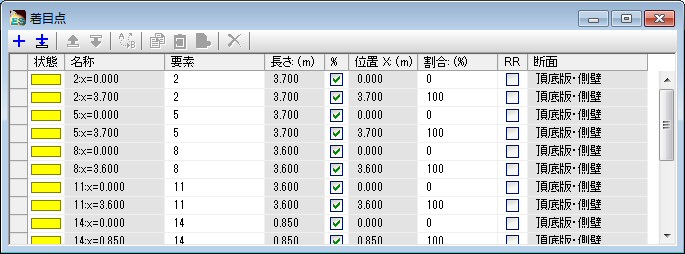
  1. Focus points for frame element
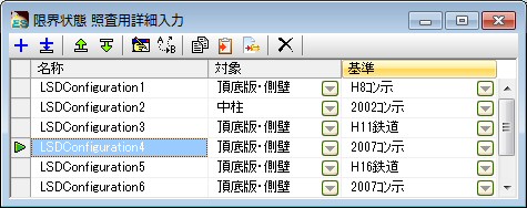
  2. Detail input list for limit state verification
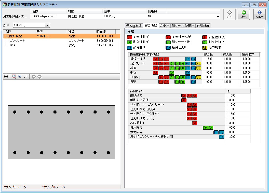
  3. Detail input property for limit state verification
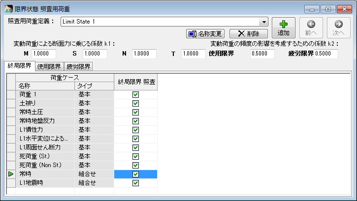
  4. Load for limit state verification
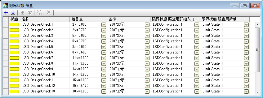
  5. Limit state verification list (Figure 3)

画像をクリックすると大きな画像が表示されます。 画像をクリックすると大きな画像が表示されます。
Figure 2 Input of focus point Figure 3 Detail input list
for verification of limit state desitn

画像をクリックすると大きな画像が表示されます。 画像をクリックすると大きな画像が表示されます。
Figure 4 Detail input property for verification of limit state design Figure 5 Load for verification of limit state design

画像をクリックすると大きな画像が表示されます。
Figure 6 Verification list of limit state design

The verification list of figure5 above is the unit for verification. The structure is as follosings.
  [Verification list] = [Focus points] + [Detail input list] + [Load definition]
Since there are a lot of input in the detail input list, input is performed in the special screen (Figure 4).

Since the several load cases can be specified at the same time in the load for verification, a lot of load cases can be verified in one limit state design list.

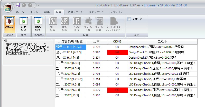
The verification results will be displayed at the rate like Figure 7, 8. Figure 7 is the summery. In this summary table, the strict results will be extracted and displayed from each verification. The detail results for each verification are as figure 8 below. Clicking the fields of rate in both figures can sort them in both ascending order and decending order.

画像をクリックすると大きな画像が表示されます。   画像をクリックすると大きな画像が表示されます。
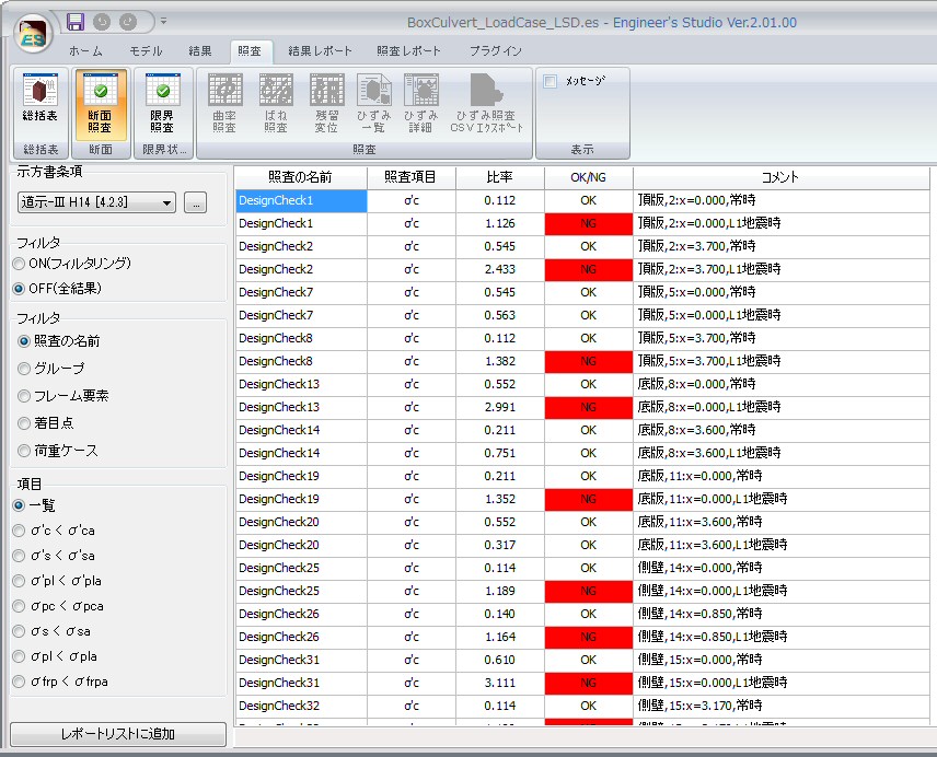
Figure 7 Verification and summary table of limit state design   Figure 8 Verification result of limit state design

Setting for repot output is performed as shown in figure 9. The detailed calculation sheet including the calculation formula can be output. Since the number of paper for output will be increased, the items to output can be selected.

画像をクリックすると大きな画像が表示されます。
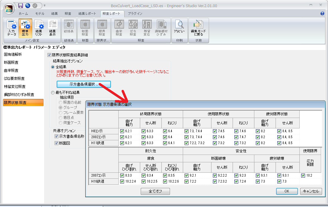
Figure 9 Setting of reoirt output of limit state design
 M−θmodel of NEXCO Design Scheme, July 2012
The method to model the relationship between bending moment and rotation angle (M−θ) in tri-linear as non-linear characteristic of base of bridge pier in the second chapter of NEXCO Design Scheme is shown. In this edition, the M−θ relationship of tri-linear is automatically created to the spring characteristic by working with the cross section.
Plastic hinge length Lp, yield displacement δy, displacement of limit state δls2 is applied to Specifications For Highway Bridges 2012 seismic design and auto-calculated.

Auto-generated M−θ characteristic can be confirmed on the screen of the spring characteristic. Allowble rotate angle θpa2 is calculated with the formula (3-2-4) of design scheme p.3-27 and used for the verification of the spring element.

画像をクリックすると大きな画像が表示されます。
Figure 10 M−θinput of NEXCO design scheme chapter 2

画像をクリックすると大きな画像が表示されます。
Figure 11 M−θ historical model of NEXCO design scheme chapter 2
The transition from UC-win/FRAME (3D) and future prospects
Ver 2.01 supports the limit state design code. In addition to the new functions, it includes the major functions and this it the important release for this product. Moreover, we have already announced that the new maintenance contract of UC-win/FRAME (3D) will not be conducted. It can be said that this is the big step forward for a lot of users. Here we will introduce about this transition.

The function comparison with UC-win/FRAME(3D)
Engineer's Studio® was developed from a source code of UC-win/FRAME(3D) and both software still share the solver. As for the former, added interface has been added and the new infinite element has added to the solver, and it is aimed to the comprehensive FEM modelling and providing the platform which is more compatible with development.
Data fila of whole version of UC-win/FRAME(3D) can be directly imported with Engineer's Studio®.
Below is the improved points and supported items compared with UC-win/FRAME(3D).
Engineer's Studio® was developed from the source code of UC-win/FRAME (3D) and the solver is shared for the both software.★
  • Graphical edit tool has been developped. The response for the large scaled model has significantly been improved from UC-win/FRAME (3D).
  • The data creation time can now be reduced by implementin the effective function and operation system for creating models.
  • New finite element which enables to model the wide range has been added. (Mindlin flat plate element, ccatenary cable element, viscous damping element etc.)

Scheduled development
The key functions under development are as follows.
  • Multiple dynamic external force load
  • Multiple dynamic external force displacement load
  • Multiple acceleration load
  • Refusal of results to save

Previously, all of the result of solver had to be saved into a disk at the time of designing by UC-win/FRAME (3D), however, it is getting difficult to do it because of the larger scaled model. Although the same saving method has been adopted in Engineer's Studio® so far, the function for refusal of saved results has now been developed. In addition, multithread of result processing is planned to be developed and the significant improvement for saving the whole processing time can be expected.

Future prospects
Engineer's Studio® has been designed as a platform considering the consecutive expansion of FEM analysis and design.

Some request from users unfortunately could not be realized so far in UC-win/FRAME (3D), however, the new library for Engineer's Studio® became more effective and development of Engineer's StudioR can now be more focued on than before because of the reason the development of UC-win/FRAME(3D) has been halted. That will be able to handle requests from now on.

We understand that our customers have to learn the new GUI though, the traning video to smooth the transition to Engineer's StudioR has already been prepared.

We are hoping that you will try to overcome this and enjoy its benefit.
(Up&Coming '13 Spring Issue)
戻る
Up&Coming

FORUM8