New Products & Service Simulation 
UC-win/Road Ver.13.1
3D Real-time VR Simulation
●Price

●Release
Ultimate: $19,200  Driving Sim: $12,800
Advanced: $9,700  Standard: $6,300
May 2018

 Enhancement of the online map data import plug-in
UC-win/Road Ver.13.1 has a function to easily create buildings and forests by importing map data available on the internet. The OpenStreetMap and GIS (Geospatial Information Authority of Japan) map are planned to be supported.

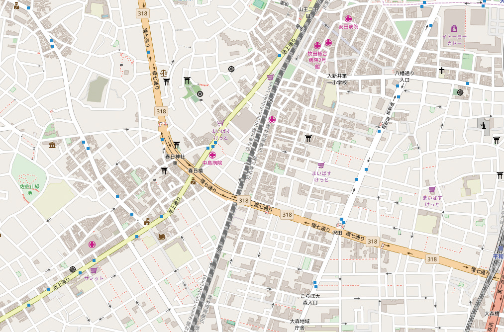
The OpenStreetMap is a project that volunteers create a freely available map on the internet. The map created in this project is open on browsers and free to use on websites. The vector data can be used for the purpose of merchandise too.

The GIS map is provided by the Geospatial Information Authority of Japan (GIS). The users have to obey the terms of service defined by the GIS to use the high-precise map data.

To import online map data, first define a zone where you want to download a map. Click the import button in the zone edit screen. The data will be automatically downloaded, and buildings and forests are displayed.
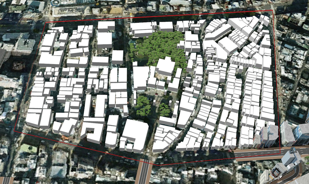
画像をクリックすると大きな画像が表示されます。 画像をクリックすると大きな画像が表示されます。
Fig.1 OpenStreetMap data Fig.2 Map data imported from the OpenStreetMap

If the height data is included in the map data, objects at that height are created. If not, the default height is used. The created buildings and forests can be edited.
Users can edit models one by one or the whole buildings or forests. For building objects, height, colour, and model category can be changed. For forest editing, kind and number of tree, height, and rotation angle can be selected.

Since more objects than you required may be created depending on the map data, users can select whether to create each building and forest model or not.

The development to import map data services other than the OpenStreetMap and GIS map is ongoing. Please let us know a database you want to use.

画像をクリックすると大きな画像が表示されます。
Fig.3 Editing after import
 Parallel road generation process
Parallelizing the road generation process performed when completing the road edit and terrain edit shortens the time of calculation in the multicore CPU environment.

Road shapes to be created according to terrains, road aligns, and road sections are calculated in the road generation process and recalculated when editing terrain and road. This process takes time when there are many roads and large terrain, and it was one of the reasons of less efficiency.

These days, multicore CPUs typified by the Intel Core i series are widely spread, and the parallelized process to decrease the whole calculation time is possible by dispersing the process on multiple CPU cores. In the version 13.1, this process contributes to decreasing the time of road generation in the multicore CPU environment. In the developing version on 6 cores CPU, the computing time has been shortened to 1/3 to 1/4, and the same extent of time reduction is expected in the product version.

We will consider the parallelization of other time consuming processes in UC-win/Road to improve the processing speed.

画像をクリックすると大きな画像が表示されます。
Fig.4 Parallelized process
 Improvement of the point cloud modeling plug-in
LOD
Hundreds of millions of point clouds can be treated in the 64bit version, and LOD display of point clouds enables the more comfort and efficient use of these numerous point clouds. In the 3D view, scenery around the view point is displayed with the original point cloud density, and faraway place is displayed with rough point clouds. In addition, to prevent the scenery looks rough, places with high point cloud density is roughly created on a priority basis when simplifying the distant data. It seems that the point cloud data would miss in the distance, but it cannot be seen actually. In the rendering option tab, the start distance and the end distance can be changed, and the LOD level is adjusted in stages between the selected distances. The default start distance is 50m and the default end distance is 500m. The display performance depends on the PC performance, but the 400 million point cloud data can be displayed in more than 60fps.
画像をクリックすると大きな画像が表示されます。
Fig.5 Point cloud with 162,700,000 points
 Model integration
Projects updated many times includes at least extra model data or section data. They consume lots of memory in the machine and do harm to the work performance. This function focuses on the similarity of imported data and detects deletable data. The detected similar data are considered as an alternative to each other and can be integrated if users want. This feature will save the memory during working, compact the project file volume, and improve the usability in the project operation.
 Improvement of convert precision of latitude, longitude, and right angle coordinate
In UC-win/Road Ver.13.1, more precise data can be created by converting the geographic coordinate system (latitude and longitude) and projected coordinate system (plane right angle coordinate system and UTM coordinates) held in project data.

The current convert of the geographic coordinate system and projection coordinate system is done by saving each value on the origin and the diagonal point at the beginning of project creation, considering each axis direction as north, south, east and west, and complementing line shapes. However, in fact, the rectangle in the geographic coordinate system becomes a trapezium in the project coordinate system and does not match the four points of the compass since an oval earth is projected on this coordinate system. This convert result is not the correct value, but it is not a big problem on VR.

However, the kinds of terrain data have been increased, and the UC-win/Road is now adopted to a lot of projects in addition to VR. Moreover, the information circulation of 3D data is getting common also in the civil engineering field. Considering these facts, this error cannot be ignored anymore. In the UC-win/Road Ver.13.1, latitude and longitude are precisely converted from the coordinate on UC-win/Road by using the coordinate system data in project data.

画像をクリックすると大きな画像が表示されます。
Fig. 6 Converting longitude and latitude and plane right angle coordinate system

When a new project is created in the UC-win/Road Ver.13.1, height data of latitude and longitude grid is not imported as it is. Latitude and longitude for grids in UC-win/Road are computed first, and more precise terrain data is created by complementing heights corresponding to those points from the original data. This is also supported for import of the GIS tiles and Geotiff. In addition, calculation of longitude and latitude by the new convert provides more precise values in the UC-win/Road Ver.13.1.

SDK developments also show promise of data utilization because of the precise coordinate convert by using the coordinate convert function.

Moreover, we are enhancing the UC-win/Road for the linkage with the developing CIM cloud solution service and next generation VR-Cloud® that is being reborn.

 Enhancement of multi user function
The multi user function has been enhanced in UC-win/Road Ver.13.1. Until now, the simulation calculation period on master side was determined in the composition of cluster master and cluster clients, and each client computed according to the master's time. In Ver.13.1, a timer (processing by time) can be set, and this function is important to link multiple HIL systems. Synchronization of HILS timers is difficult, and most HILS cooperated with clients do not work according to the master timer. To solve this issue, clients can now work in accordance with cooperating HILS timers.
(Up&Coming '18 Spring issue)
Back
Up&Coming

FORUM8