New Products & Service Simulation 
UC-win/Road Ver.14 4D Simulation
Simulate changes according to the flow of time by adding time axis data to 3D simulation
●Price
●Release
TBD
2019

 Product overview
4D simulation functions are planned to be developed for UC-win/Road Ver.14.
 Purpose
A 4D simulation is a function to simulate how environments change depending on the flow of time by adding time axis data to a 3D simulation. It can mainly be applied to depicting changes according to construction and architecture projects and visualizing manufacture flows in factories.

画像をクリックすると大きな画像が表示されます。
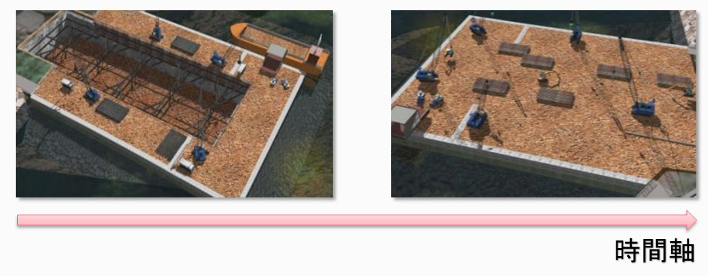
Fig.1 4D simulation (time axis)

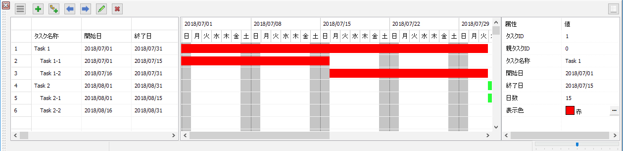
The existing UC-win/Road has the "Visibility" function to depict changes in projects due to time flow. This function allows users to make landscapes of certain times such as "Now", "Before", and "After" to depict changes of environment according to time by showing or hiding models. Since this function just switches model displays specified in the visibility setting, it cannot show a state at a specific time between the set times. A stream of time cannot be displayed in video neither.

To show a flow of time in video, scenarios can be used to express it in animation, but settings to create a 4D simulation is difficult because the scenario function is a function used for general purposes. In addition, a condition at a certain time cannot be checked later. As we described above, this feature is not enough for the 4D simulation.

For UC-win/Road Ver.14, we will develop a 4D simulation function in order to reproduce changes on projects including time data in addition to 3D data.
 Gannt chart definition
The data definition of time axis will be displayed and edited in a Gannt chart format.

画像をクリックすると大きな画像が表示されます。
Fig. 2 Gantt chart setting

In the Gannt chart definition, users will create tasks equal to contents of one work and visualize the work contents by entering the starting and ending time of tasks. Multiple subtasks can be set to one task so that users can manage and grasp their works easily.

For this task data definition, we will add a file input and output function. Files exported from table calculation software will be able to be imported, and this will enable a cooperation between software programs.

Fig.3 Task data file format
 Definition of 3D model move
To make a motion definition of 3D model, add model data and model movements to tasks. Model movements can be defined by defining at least one coordinate data at a specific time. Model movement between specified times will be complemented and calculated. The definition by a program input and a file loading will be corresponded.

画像をクリックすると大きな画像が表示されます。
Fig.4 Definition of 3D model movement
 4D simulation
When a play button on the gantt chart is clicked, models are displayed on coordinate positions where the models will be at each time according to 3D model movements defined in tasks. The animation speed can be changed, and users can check the positions of models at a specified time by changing the time on the gantt chart.
 Conclusion
In this topic, we introduced the 4D simulation function planned to be developed in UC-win/Road 14. We will progress the development of UC-win/Road including a visualization of each 4D data and a construction simulation for further use. In addition, we are thinking to visualize changes of properties according to time flow. Please feel free to contact us if you have any requirements or inquiries.
(Up&Coming '18 Fall issue)
Back
Up&Coming

FORUM8