| SUPPORT TOPICS |
Question & Answer Forum - VR
|
Maintenance/Support Service
Related Information |
| UC-win/Road |
|
| How to control the number of traffic when you widen the roads |
|
In this section, we will answer comparativery many qustions out from your
inquiries about UC-win/Road. This time, we answer about "How to set arbitrarily the number of
vehicles running when widening of road by UC-win/Road.".
When widening of road, the number of vehicles is nomally devided evenly.
If you want to set the situation that after widening of road, the left
lane will be left-turning only and the number of vehicles will decrease
or the number of vehicles running right-turning only lane will increase,
follow this process.
This process is on the assumption that there are two lanes each way and
the number of running vehicles is 200.
| A: |
This Explanation is for the case that you want to control the number of
left-turning vehicles 30 on the assumption that one lane increased just
before the junction. It is assumed that the sections have already been
prepared. |
|
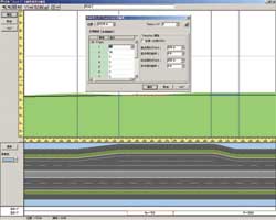
1. |
Edit Transition section which the number of lanes is increase, in Edit
vertical linear screen. |
|
2. |
Change the weight of each lane. As 100 vehicles run one lane, enter 30
for lane1 and 70 for lane 2. |
|
3. |
In 3D space, vehicles run in 30, 70, 100 ratios from the left traffic lane
after this widening of road position. |
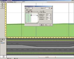
| B: |
Another explanation is for the case that one lane increase right side.
It is assumed that the right-turning lane increase on the medial strip
side and the number of right-turning vehicles is 40. |
|
1. |
Edit Transition section which the number of lanes is increase, in Edit
vertical linear screen. |
|
2. |
Change the weight of each lane. Now enter 60 for lane 1 and 40 for lane
2. As the lane number is considered based on the point where the lane increase,
the far left lane is ignored and enter only for right lane and increased
right-turning lane. Note that the lane number is not correspond to the
lane order starting from the left. |
|
3. |
In 3D space, vehicles run in 100, 60, 40 ratios from the left traffic lane
after this widening of road position. |
Using Transition here, you can provde different specific gravity every
vehicle with a specific profile, such as large-size vehicle, for a traffic
lane. Please make use of this feature within the various traffic control. |
  |
Page Top 
|
| SUPPORT TOPICS |
Question & Answer Forum
- Dynamic Analysis
|
Maintenance/Support Service
Related Information |
| UC-win/FRAME(3D |
|
| What should be noted in using fiber elements? |
|
Fiber element segments section into mesh and give hysteresis (stress-strain
relation of materials) to each cell. The hysteresis of materials support
concrete/reinforcing/plate and steel/prestressing steel/fiber reinforced
sheet(* There is a hysteresis expansion option partly).
For modelling, it is necessary to choose the appropriate hysteresis for
the charasteristics of the members. For example, when you check the reinforced
concrete pier according to Specifications for highway bridges V aseismic
design, you must select "Hoshikuma (the model which can consider wide
restriction effect by tie)"for the hysteresis of concrete
UC-win/FRAME(3D) supports "the original", "the second" and "the
1st" for fiber elements. It is difficult problem that how to set the
length of fiber elements, but set them based on following properties.
●The original :
UC-win/FRAME(3D) original fiber element assume half section to be curvature
uniformity. Based on the plastic hinge length Lp which can be obtained
from Specifications for highway bridges V aseismic design, set the length
to about twice as long as it. If the element length is extremely short
or long, since it can't be converge or kept its accurancy, the program
checks whether the length of fiber element is in the range from 0.5 time
to double of the section height (the smaller width and height) and displays
warning if it is out.
●The 2nd :
This element is isoparametric element (3 nodes, truss element) which is
often used in finite element method. The displacement function and the
shape function of the element was given by same quadratic polynomial. The curveture distribution wii be linear curve.
●The 1st :
This element is isoparametric element (2 nodes, truss element) which is
often used in finite element method.The displacement function and the shape
function of the element was given by same linear polynomial. The curveture distribution will be constant with element length.
The appropreate mesh number of pertitions of section height direction is
about 20 only as a guide. Smaller mesh improve the accurancy/convergence,
but the time taken for analysis will be longer and the size of result file
will be larger. The upper limit of cell is 1000 for each section element.
By the properties of fiber elements, it can automatically consider thecoupling
of bending and axial force. It can aiso obtain high-precision solution
to biaxial bending problem by segmenting section into cell. Please use
of them. |
|
|
(Up&Coming '08 Early Spring Publication) |
 |
|


>> 製品総合カタログ

>> プレミアム会員サービス
>> ファイナンシャルサポート
|