| SUPPORT TOPICS | Question & Answer Forum - VR | Maintenance/Support Service Related Information |
| UC-win/Road |
| A method of extending a road towards its starting point |
How to add a alignment (Two way traffic)
1. Create additional line more than 2m away from exist alignment.
2. Connect them by rump alignment. Note that an alignment less than 2m can't be created.
3. Adjust plane, longitudinal section and cross section to avoid shear and bump.
This method allows you to extend a road without moving the starting point.
| 1. Create additional alignment on the starting point side | 2. Connect both alignments by ramp | |
 |
 |
|
 |
||
Page Top

| SUPPORT TOPICS | Question & Answer Forum - Dynamic Analysis | Maintenance/Support Service Related Information |
| UC-win/FRAME(3D) |
| The property of the nonlinear element (2) |
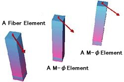
| Following the preceding issue, we are going to consider the property of
the nonlinear element. We introduced that M-θ, M-φ, fiber element model give same results in simple one-way bending state in the preceding issue. We are going to consider the result in the biaxial bending state in this issue. 250mm of forced displacement (45 degrees direction of cross section) is loaded onto the upper end of the analysis model. Its load-displacement curves (P-δ curve) are as the figure below. The result of fiber element and that of M-θ and M-φ are wildly divergent after the reinforcing bar yielded. On the computational theory, while fiber element is analyzable faithfully to biaxial bending, M-θ and M-φ elements model the sectional nonlinear property of principal axis rotation, and the P-δ curves below are seeming combination of the results of strong axis and weak axis rotation. |
 |
 |
The specifications for highway bridges V aseismic design defines that the ultimate limit is when the strain at the position of compression reinforcement reaches the ultimate strain. By the result of fiber element of UC-win/FRAME(3D), it is determinable as ultimate displacement δu = 78.5mm.
However, δ = 230mm that is determined as ultimate with M-θ and M-φ elements is almost three times the result of fiber element, and at this time, the strain level of concrete and reinforcement are as below.
For example, the analysis result using M-θ and M-φ elements exceed the ultimate strain substantially, and furthermore, the state that the reinforcement yielded could be ultimate.
 |
We analyzed the model, 45 degrees direction of square section, which is most affected by the biaxial bending this time, but in practice, it is important to consider when using M-θ and M-φ elements in case of biaxial bending occurs.
UC-win/FRAME(3D) provides the 3 elements above, so it is relatively-easy to consider preliminary. Please make use of it.
We are going to consider the case which axis power vibration occurs in the next issue.
 |
 |
 |
||
| BACK | INDEX | NEXT |