In the latest SFHB, the type I waveform at the time of earthquake level 2 has been refreshed. All of the necessary waveform for the dynamic analysis are saved into the folder in which the product has been installed (C:\Program Files \FORUM 8\Engineers Studio 2.0.0\Samples\Waves\).
Figure 1 is the necessary input screen for M−φ of reinforcement concrete section, where the values regarding the allowable strain of reinforcement are input. For the stress strain curve of concrete, the conventionally ultimate strain 0.8σcc has been changed to 0.5σcc. M−φ characteristic (Figure 2) can be obtained from these conditions. This is the non-linear history model of bi-linear type specified by SFHB.
 |
 |
| Figure 1 Input screen to calculate allowable strain εst |
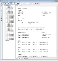
Figure 2 M−φcharacteristic of reinforcement concrete section |
The necessary input screen for M−φ of steel pier section is figure 3. This is in case of rectangular cross-section which is not concrete filled, where input regarding the allowable strain εa of steel pier. The non-linear history model is as shown in figure 4.
 |
 |
| Figure 3 Input screen for calculating the allowable strain of steel pier cross section |
Figure 4 M−φ characteristic of steel pier cross section |