New Products & Service Simulation 
UC-win/Road Ver.13
 UC-win/Road VR Seminar
Date: 9:00 - 12:00AM, April 13, 2018 (Japan time)

On the Web
Participation Fee: Free
3D real-time VR simulation
●Price


●Released date
Ultimate: US$19,200
Driving Sim: US$12,800
Advanced: US$9,700
Standard: US$6,300
December 2017

 UC-win/Road Ver.13

In Ver.13, we developed a number of new features including: Earthwork volume calculation, Enhanced VR data creation and Enhanced simulation functions. In addition the interfaces for HTC VIVE and UAV drones have been improved.

 Earthwork volume calculation

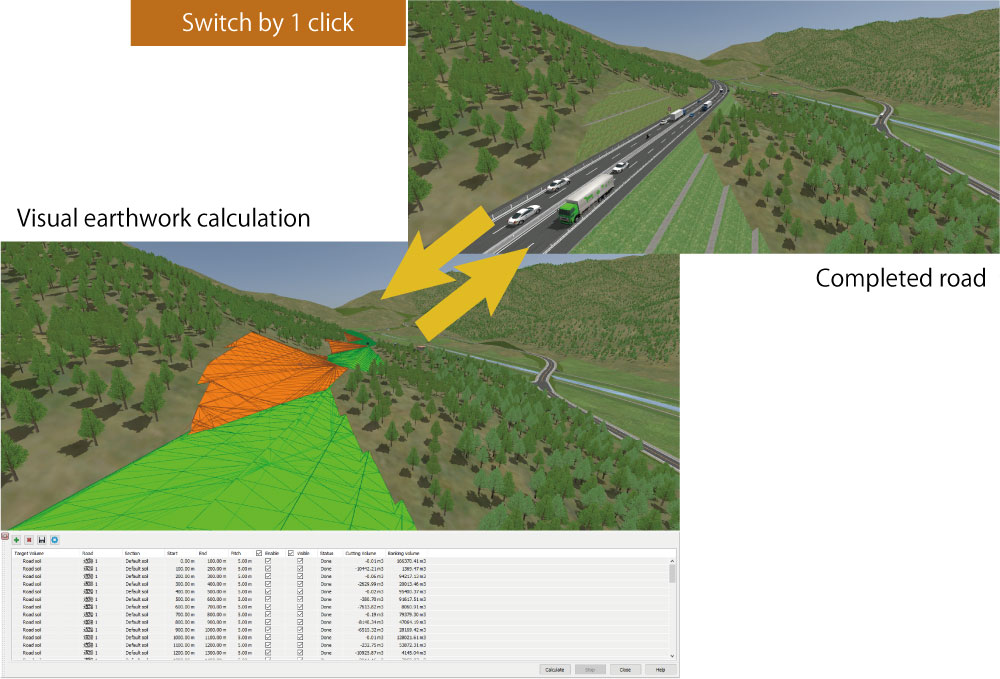
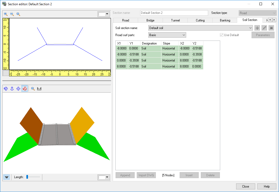
The earthwork volume calculation function has been added to the UC-win/Road Ver.13. This function allows users to calculate approximate volume of the earthwork by using the 3D shape of roads and terrains created in the software (Fig.1).

The use of 3D data in the civil engineering industry is becoming far more popular. This new calculation function uses the 3D shape of the earthworks for calculation instead of the common average section method.

After the intersection of road and terrain is calculated, roads are divided into two areas. One is the field where the road surface is higher than the terrain (banking), and another is the area where it is lower than the terrain (cutting). The volume between both surfaces is calculated by using the divided 3D surface shape data.

For calculating road surfaces, users now can select cross sections for civil engineering instead of the existing road cross section setting. The construction foundation and the embankment and cutting can be defined as with the current road cross section definition. Since default civil engineering cross section is automatically generated from existing road section, the volume of earthwork can be calculated after the normal data creation without any additional inputs (Fig.2).

The amount of soil can be calculated by entering the road, earthwork cross section, distance from beginning to end, and pitch of the road surface. Users can define these items one by one, but also can use a batch creation function when calculating earthworking volume by a constant range or each cross section. Calculation by section enables the calculation of the cost including the amount of soil volume in each block. It can also be used for comparative review of different cross sections by using multiple earthwork cross sections.

Click to enlarge the image.
Fig. 1 Earthwork volume calculation
Click to enlarge the image.
Fig. 2 Section editor
Click to enlarge the image.
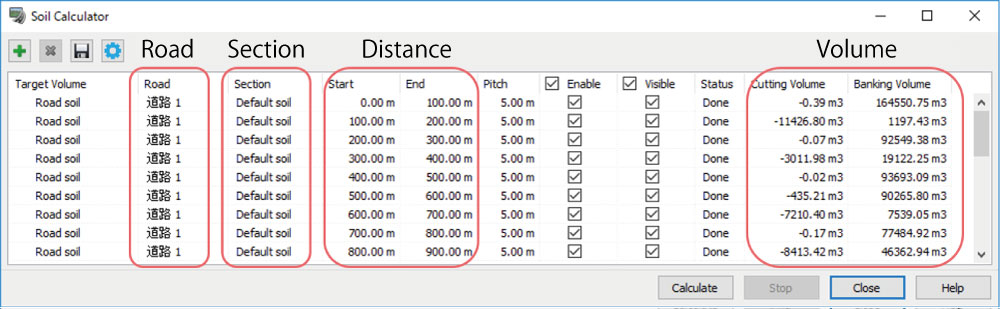
Fig. 3 Soil calculation setting

Cutting volumes and banking volumes are displayed in the Soil Calculator screen after executing the calculation. When the display in 3D screen is enabled, cutting and banking surfaces are displayed in the colors you selected. Calculation results can be output as comma-separated and tab-separated CSV files to link with table calculation software.

This new function in Ver.13 is designed for the approx calculation of the amount of earthwork. We will continue to develop and enhance this function to include the calculation of the volume of structures and for the creation of land.

 Enhancement of data creation

Improvement of road modeling
The edit function in the "Road Section Details" has been enhanced to reduce the cost of data creation. Since the design of road cross section has become simple, it is now possible to reduce the number of sections in the project. Specifically, the following three items have been improved.

  1. Users can freely insert and delete carriageways and white lines / zebra zones between lanes as required. Your edit is immediately reflected on the 3D preview so that you can check your edit result quickly. Dummy carriageways (width = 0 m) set in files created in the previous versions are automatically updated, and it creates a simple road section structure.
  2. You can freely adjust scales and positions of gap and carriageway.

Click to enlarge the image.
Fig. 4 Operation screen

  1. By setting priority of decreasing the width of the carriageway and the gap at the position where the number of lanes increases or decreases, pattern of white line and zebra zone can be freely designed.
Click to enlarge the image.
Fig. 5 A flexible designing of carriageway.

Zone function
We have newly developed a zone function that allows users to define areas and to conduct various operations and calculations for the field. Borders of zones can be continuously created on the 3D screen with just a few clicks. In UC-win/Road Ver.13, acquisition of the area of zone and the max / min elevation, creation of forest and block model are available. In the future, this function will be integrated with other functions such as object selection and group creation, field usage setting, land creation function and the designation of map data import range.

Click to enlarge the image.
Fig. 6 Example of zone function usage
 Enhancement of simulation

Replay plug-in
After conducting driving experiments, videos and log data are often utilized for the analysis and explanation of driver performance and when and how and to what situation the driver reacted / responded. By playing the simulation within the 3D space with the replay plug-in, users can see what actually happened during the drive. The following three functions have been added along with improving the performance of the record processing of the replay plug-in.

  1. Sound record
    All sounds including the sound of the user's vehicle and vehicles in traffic as well as the environmental sounds and that of events can now be recorded. Since the position of the sound source is also recorded, users can hear 3D sounds from their positions within the 3D VR Space. This new function could be used to analyze the driver's reaction to a particular sound from a particular place.
  2. Automatic recording function
    On completion of the recording, the replay file (.RR) will be automatically saved to the folder selected by the user in advance
  3. Search of replay file
    Users can search the replay files in the target folder from a newly added search screen and can replay from this point. The target replay file can be found quickly by using the column option.

Click to enlarge the image. Click to enlarge the image.
Fig. 7 Search in replay plug-in

Cluster system can transmit and receive camera data
The cluster system can now transmit camera data created from the master to client side. This enables the setting of eye direction with a far higher degree of freedom by linking the camera sensor simulation on a client side to the camera sensor base plug-in on the master system. Thus it is now possible to simulate multiple cameras.

Customization for each scenario
In general, scenarios are created for each simulation when conducting several simulations in one virtual space. In previous versions of the software, it was necessary to switch the customization processing of plug-ins, developed with the system development kit (SDK), depending upon the individual experiment. However, in Ver 13 users can now call certain plug-ins from the scenarios they have created, and this makes the processing of the customized plug-in management much easier. This means that because one decides which plug-ins to use for each experiment when designing the scenarios, operators never make the mistake of selecting the wrong plug-in. This function can also be used when conducting the same experiments multiple times.

Click to enlarge the image.
Fig. 8 Cluster system transmits camera data

Expansion of weather display

  1. Addition of fluttering leaves, dust, clothes, paper, etc.
    Scenes that include wind-blown dust, including leaves and clothes can now be rendered. This function is realized using a particle system based on the speed of the wind. The speed, range, texture and the number of particles are selectable and used to create a variety of expressions. This is appropriate for a bad weather simulation and it is also possible to render falling leaves and fireworks.

Click to enlarge the image.
Fig. 9 Improved weather simulation

  1. Setting the distance of mist / fog (for Mist: Linear)
    To accurately control the viewing range within the simulation the start position of the fog and the distance of any whiteout from the camera position can be selected in meters.
  2. Enhancement of sound system
    The sound of rain heightens the realism of the simulation. Different sound qualities are used for walking and driving. The sound quality and volume changes according to the amount of rain. The purpose of this function is to reproduce the potential drop in the driver's attention caused by excessive noise, in addition to rising a sense of immersion. The sounds can be output from other audio devices connected to the special speaker by means of the scenario setting.

Click to enlarge the image.
Fig. 10 Distance of the fog

Lastly, large simulators often generate line noise on sound transmission since the sound system and simulation PC are often placed far apart. To solve this issue, the sound can be played from another PC by using the cluster system of UC-win/Road. Users can avoid this noise by setting this PC near the sound system.

 Enhancement of Device Linkage

HTC VIVE plug-in Ver.2
Functions compatible to the HTC VIVE controller have been added.

  1. Model display at the position of controller
    A 3D model you set is shown on the display and it moves according to the motion of the controller. It is useful to see the scale of motion in VR space since a model can be displayed at the position of sensor too.
  2. Function to move the point of view
    The reference point of view can be moved with the controller buttons. The VIVE provides a playing space of 5m in the diagonal, and moving the reference viewpoint lets users move around a wider VR environment.
  3. Scenario / Script menu
    In the case of the previous version, users had to take off the HMD temporarily and operate the software to play scenarios and scripts. In this version, users can display the menu and execute them from a controller.
Click to enlarge the image.
Fig. 11 Operation menu of VIVE plug-in

UAV plug-in Ver.3
The UAV plug-in can now cooperate with more different types of drones.
Additional compatible models include: DJI Phantom 4 Pro, Mavic Pro, Matrice 200 series, Matrice 600, Spark

In addition, the video streaming has been improved due to the reduction in Wi-Fi interference sensitivity and the enhancement of stability. This enables a safer and more comfortable drone flight.

A simulator mode has been added as a new function. This allows users to practice manual flight while cooperating with the VR image and simulation of flight plan without using any other applications. A periodic check can be conducted by repeating autonomous flight along the route recorded by adding passing points with a remote controller.

Lastly, planned routes using 3D space can now be exported in KML format and are available in other applications.

(Up&Coming '18 New Year issue)
Back
Up&Coming

FORUM8