| SUPPORT TOPICS | Question & Answer Forum - VR | Maintenance/Support Service Related Information |
| UC-win/Road |
| Traffic Flow Setting at the Intersection |
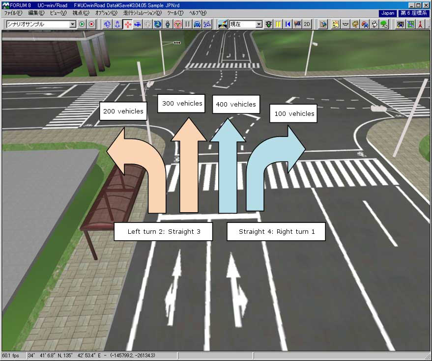
If you want to set as:
Left turn: 200 vehicles as 20%
Straight: 700 vehicles as 70%
Right turn: 100 vehicles as 10%
Given in two-lane road, you need to set as:
Left lane/ Left turn:3, Straight:3
Right lane/ Straight: 4, Right turn:1
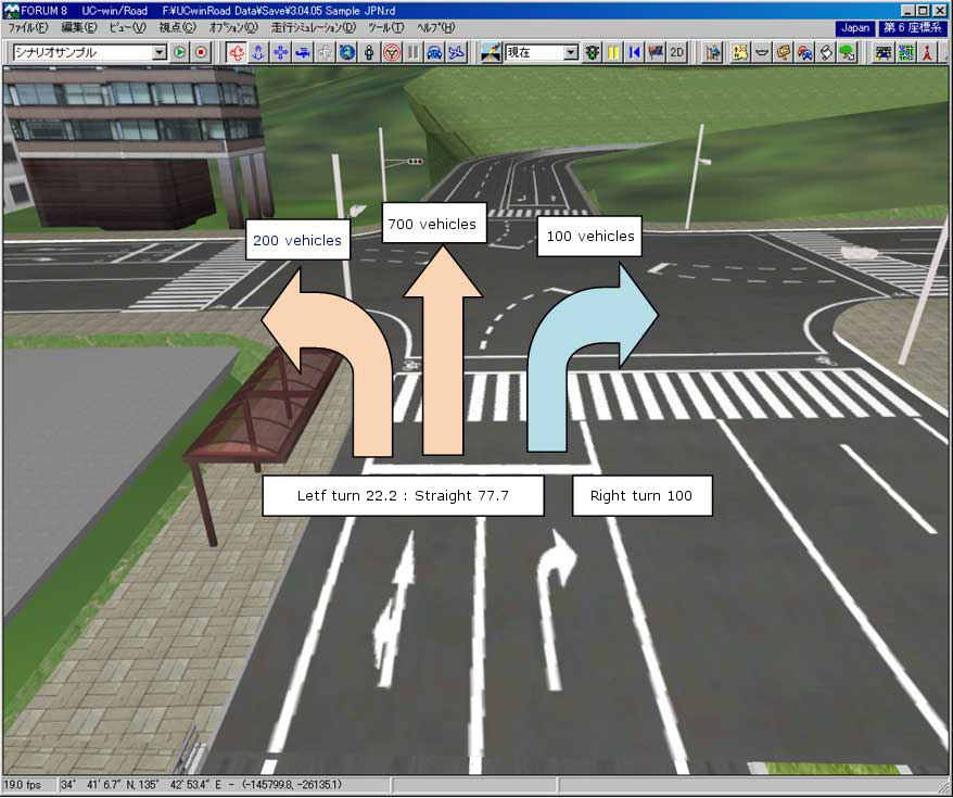
When the right-lane will become the right-turn lane, you need to shift vehicles to the left-lane until the intersection. To make the right-turn to be the 10 percent of the total share, you need to shift the 80 percent of vehicles, 400 vehicles, from the right lane to the left lane. As a result, the traffic volume will be as below.
Left lane: 90% as 900 vehicles
Right lane: 10% as 100 vehicles
Left lane/ Left-turn:22.2, Straight 77.7
Right lane/ Right-turn: 100
Above vehicle-shift setting can be set at the behavior control points. Vehicle setting is also important as well as weighting of vehicles at the intersection. For example, the number of vehicle at the next intersection depends on the weighting of assigned vehicles. If the setting of the vehicle which go straight doesn't be established, they all will drive in the left lane. There is not so much influence on the other intersection when the setting is established in the only one intersection, but if you consider a network configured by multiple intersection, you need to consider the influence.
 |
 |
Page Top

| SUPPORT TOPICS | Question & Answer Forum - Dynamic Analysis | Maintenance/Support Service Related Information |
| UC-win/FRAME(3D) |
| How can the pier with an angle of skew be modeled? |
We introduce how to export from "Seismic coefficient calculation (Bearing Design)", and how to model the pier with an angle of skew. First, when you export data from the Seismic coefficient calculation (Bearing Design) to the UC-win/FRAME(3D), the model are automatically created as following.
 |
 |
Seen from above, the model are crossed toward the super-structure and its bevelθ is 90 degrees.
To rotate pier members, two methods are available.
Method1
1) Select member(s)
2) Enter the arranged angle of section in the general tab of member edit window
Method2
1) Select member(s)
2) Right click to show the pop-up menu and select [the association between the element Y axis and the global coordinate system]
3) Enter a vector
Method1 is the way to set the arranged angle of the section for the element coordinate system, so if you enter an angle, only the main axis coordinate system rotate but the element coordinate system doesn't rotate.
Method2 is to set the angle of the element coordinate system. The main axis coordinate system rotates then; Both the element coordinate system and the main axis coordinate system rotate at the same time.
Please look at the following.
 |
The image above left shows the method1 and right image shows the method2, which is rotated. Though each coordinate system is rotated 30 degrees, the left image shows only the main axis coordinate system(subscript is p) rotating, and the element coordinate system (subscript is l) isn't rotated.
Regarding the right image, both the main axis coordinate system and the element coordinate system rotate. This doesn't influence on the analysis result, but you should take method2, for it is easier than method1.
For more information, please refer to the following help.
[Operation method | Model creations | Model(5) - the coordinate system-]
[Operation method | Model creations | Model(6) - Model (6) - The specification of the direction of the element coordinate system -]
Please make sure to rotate the coordinate system of fulcrum, when you changed the angle of pier.
If you forget to change it, as the right image showing, the footing and the fulcrum can't match.
 |
Functions introduced above are effective for you to create skew bridge models or curved bridge models.
Please make use it.
 |
 |
 |
||
| BACK | INDEX | NEXT |