| 3 dimensional dynamic non-linear analysis |
Followings are the revised points of UC-win/FRAME(3D) Ver.4.00.00
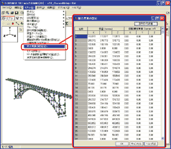
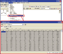
- Spread sheet style data entry of joint mass
- Initial section force
- Eigen value analysis of geometrical rigidity
The older versions set mass points by making rigid body element with 1 joint and giving mass.
The method required creation of rigid body element and customers had to open edit screen of rigid body element every time you need to define mass points. Spread sheet style input reduces this bothering work. You don't have to generate rigid body element for mass points any more.
Giving mass points by spread sheet style enables the value to be reflected to dead load and horizontal seismic coefficient, which are calculated by the program automatically.
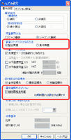
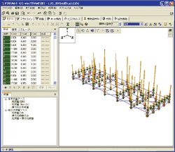
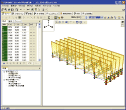
If you select concentrated mass on setting screen, dead load and horizontal seismic coefficient are reflected to concentrated load to the joints. (diagram 2,3) If you select consistent mass, it is loaded as distributed load to members.(diagram 2,4)
 |
 |
 |
||
(concentrated mass to joints) |
(distributed mass to joints) |
Consistent mass is one of the method of mass matrics, which is adopted by this program since its release.
Consistent mass is calculated by differentiation. In Japan there are a couple of translation of consistent mass.
Consistent mass method can calculate vibration characteristics with less joints and is more accurate compared with concentrated mass. However, in this program, consistent mass is generated automatically by processor.
Customer have to check the value. You can output each joint mass to report, by giving enough joints to generate vibrarion characteristics and calculating joint mass with concentrated mass method.
Both calculating by concentrated mass method and consistent mass method lead to the same total mass.
However, displacement of member is generated because displacement of member occurs by assuming initial section force is in member.Because displacement at joints does not occur and displace ment of member occurs, displacement of member at i edge and j edge is zero.
Setting screen of initial section force has a button to select a certain load case and perform calculation.
When you press the button, UC-win/FRAME(3D) performs elastic analysis and adopts section force of i edge and j edge as initial section force. In this manner, the system adopts section force at the edge, condition of section force distribution inside members is ignored. Therefore, condition of section force distribution, which is loaded member load including distributed load or non uniform distributed load, does not match the condition to which they are adopted as the initial section force. To make this inconsistency smaller, select the load case with joint laod or make a model with a lot of joints: model in which member is finely divided. This condition is also true to the case using the section force calculated by other program.
Eigen value is calculated by using rigidity matrics[K] and mass matrics[M]
and solving |[K]-ƒÖ2[M]|=0 for eigen vibration value ƒÖ.
The older version used rigid matrics of linear elasticity [K0] for rigid matrics ([K]= [K0]).
The new version allows you to consider geometric rigid matrix[KG].
In case considering the geometric rigidity, [K] is given by [K]= [K0]+[KG]
You can specify the setting in "eigen value option" on model setting screen.
Setting initial section force is necessary for generatiing [KG].
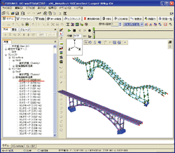
Sample model "s06__MetalArch.f3d"(matal arch bridge) of the product shows the result of 0.683Hz without considering geometric rigidity, while 0.664Hz by considering geometric rigidity.
The result of in consideration of geometric rigidity generated eigen value approximately 3% smaller than that of without considering geometric rigidity. (diagram 6). It means that eigen natural period generates larger value by 3%.
However, in this examination, weight of sample model is made heavier by 40% in consideration of panels and bolts.Eigen mode is the result of considering the linear mode(anti-symmetrical linear mode in bridge axis direction) "Guideline of earthquake resistant design of metal bridge" says 4-5% difference is generated in arch bridge calculation.
 |
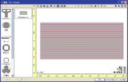
Vertical and horizontal division option was added to meshing methods of fiber element section.
(e.g. meshing 1 for horizontal and 20 for vertical) (diagram 7) Reduced calculation time is expected in case of in-plane analysis.
 |
These revisions are refelecting request from a lot of customers. Since important functions of analysis will be added in this version, we expect more and more customers can use UC-win/FRAME(3D) for analysis which could not be solved by the previous version.
