|
|
1. Engineer's Studio® Ver.3
2. International version of analysis support service
3. Overseas Training and Seminars
|
| 1. Engineer's Studio® Ver.3 |
The followings 7 items are supported in Engineer's Studio® Ver. 3
The Japan Society of Civil Engineers Standard specifications for Concrete
Structures-2012 and cross-section verification of beam elements
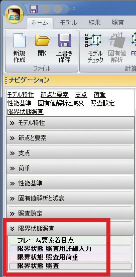
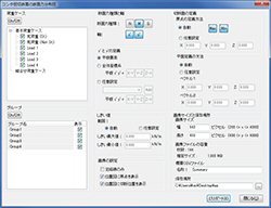
Each of the following are supported: Verification of durability [steel corrosion- (bending / shear / torsion) crack] and usability [stress limit, appearance of a crack - (bending / shear / torsion)], assessment for safe section destruction (bending / shear / torsion) and safe fatigue failure (bending / shear).
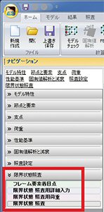 |
| Figure 1 Input of the limit state design |
Feature to generate a mass from a load
This is a feature to automatically generate the mass of an element sitting on a node point by specifying the user-defined load (basic load case) applied to the node point. However you cannot specify the dead load (St) automatically generated by the program, dead load (Non.St.) itself, prestress load, horizontal seismic load and combined load.
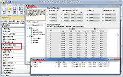 |
Figure 2 Window in which
you can enter in parameters
required to convert from load to mass |
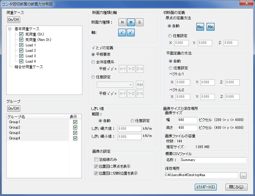
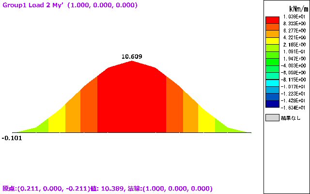
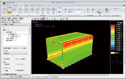
Ability to export a graph showing the section force distributed within
the cutting plane of the flat plate element contour map.
This allows you cut out your favorite piece of the flat plate element contour
map and then visualize the section force distributed within the cutting
plane in 2D. In doing so several image files (*.png) and numerical data
(*.csv) indicating the in-plane axis force, out-of-plane bending moment,
and out-of-plane shear force will be exported and saved within the specified
folder.
 |
|
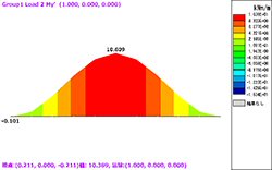 |
Figure 3 A graph showing section force distributed
within the cutting plane of the flat plate element contour map |
Importing and exporting CAD data (DXF / DWG format)
This is a feature to export a graph showing section force distributed within the section geometry or the entire frame model to CAD data (DXF / DWG format), and to import a frame model from the CAD data.
A list showing the damage done to the fiber elements
This is a feature to display the damage done to the fiber elements with colors and numeric values that indicates whether or not the damage level (strain) exceeds the one prescribed in the law of hysteresis.
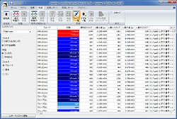 |
Figure 4 A list showing the damage
done to the fiber elements |
A list showing the section force, analyzed by FEM analysis, acting on the
frame element
The list shows the section force acting on the frame element as the result
of FEM analysis. The data in this list is indeed the data that is input
when the program runs across section calculation. The analysis results
of the section force and the data that are actually input, both have the
same value, however, in the case where the centroid of the cross section
is moved, or in the case of PC member, the values will be adjusted so as
to make sense.
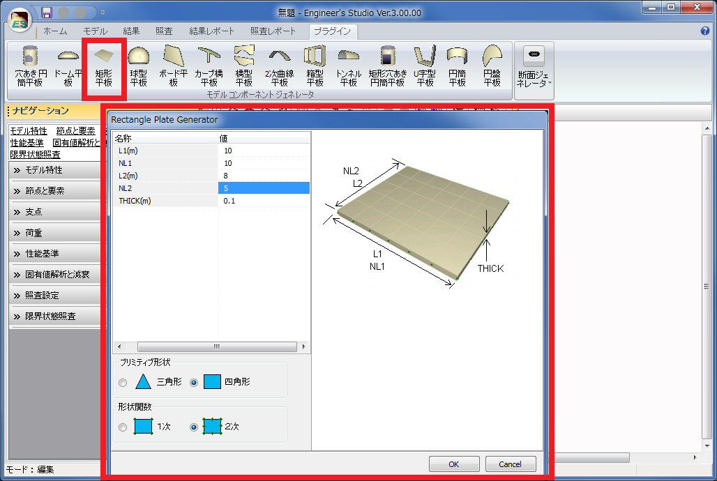
Plug-in for creating plate element "Rectangle plate"
A plug-in designed to generate a component with plate element has been improved in that even rectangles with two pairs of the opposite sides having different lengths can have their geometry input.
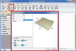 |
| Figure 5 "Rectangle plate" plug-in |
|
In addition, the following features have also been added.
- The ability to make settings required to perform cross-section verification
against the target points on a number of frame elements with few clicks.
- The range can now be specified when using the "Divide frame element"
command (Previously, only the number of equal parts into which the frame
element is divided could be specified).
*These features help the generation of a plate element (mesh elements).
In concrete terms, if you divide the frame element and then create a plate
element on the both sides of the frame element, the 2 plate elements can
share the nodal points on their boundary.
- A feature to assemble the several node points and elements intermittently
selected into one place.
- A feature to save view points.
* The details of the saved viewpoint can be invoked anytime as it is available in both the input mode and results mode. |
| (Up&Coming '13 Summer Issue) |
| 2. International version of analysis support service |
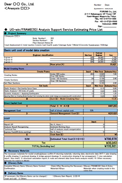
This international version of the "UC-win/FRAME(3D), Engineer's Studio® Analysis Support Service" and" Geo Technical Analysis Support
Service" (available in English, Chinese, and Korean) is for users
outside Japan that are using UC-win/FRAME(3D), Engineer's Studio®,
Geo Technical Analysis series (GeoFEAS3D, UWLC, LEM3D, VG-Flow), and users
in Japan that are taking orders for the work to be conducted outside Japan.
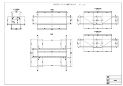
Since 2004, FORUM8 has provided this analysis support service to more than 500 users and it is the kind of business achievement we are proud of. We provide a high quality service by using state-of-the-art analysis methods such as the Dynamic Nonlinear analysis and Geo Technical Dynamic FEM Analysis, providing customers with accurate analysis results on various types of civil works and architectural structures. The products targeted for this service are UC-win/FRAME(3D), Engineer's Studio®, and Geo Technical Analysis series (GeoFEAS3D, UWLC, LEM3D, VG-Flow) are being localized to English and other languages for the worldwide market, and are highly regarded by many prestigious Universities in Japan as excellent Japanese software. The work flow of the service is the same as that of the Japanese version. Customers prepare the structural drawing and other materials required for quotation, after which our technical team produce the quotation.
|
|
|
Delivery |
 |
|
 |
| Creation of analysis
data |
|
 |
Figure1 The flow of this service |
|
|
|
| 3. Overseas Seminars and Exhibition |
Exhibition
| Date |
Exhibition Name |
Location |
| 16 Sep. - 19 Sep, 2013 |
SimTect |
Brisbane, Australia |
| 18 Sep. - 20 Sep, 2013 |
FORUM8 Design Festival |
Tokyo, Japan |
| 30 Sep. - 2 Oct, 2013 |
European Transport Conference |
Frankfurt, Germany |
| 8 Oct. - 10 Oct, 2013 |
InterGeo 2013 |
Essen, Germany |
| 15 Oct. - 18 Oct, 2013 |
ITS WORLD CONGRESS TOKYO 2013 |
Tokyo, Japan |
| 30 Oct. - 31 Oct, 2013 |
CONVR 2013 |
London UK |
| 21 November, 2013 |
Award ceremony for the 3rd Virtual Design World Cup
and the 1st Cloud Programming World Cup |
Tokyo, Japan |
For more information and applications, please email us at
mailto : office@forum8.com
The 3rd Student BIM & VR Design Contest on Cloud and the 1st Student Cloud Programming World Cup have been decided to be held. The overviews can be seen on FORUM8's website. If you got interested in these contest, do not hesitate to contact us and register!
|
Application term / Schedule
|
| Registration Period |
June 13 (Thu) - September 30 (Mon), 2013 |
| Project Submission Period |
October 1 (Tue) - October 10 (Thu), 2013 |
| Judging Period |
October 15(Tue)-October 24 (Thu), 2013 |
| Announcement for nominated work |
October 25 (Fri), 2013 |
| Award Ceremony |
October 25 (Fri), 2013
Megro Gajoen 2F "Maiogi"(MAP) |
|

 |
Gross circulation:6743
To subscribe this page, go to http://www.forum8.co.jp/english/p-mail-e.htm
If you would like to unsubscribe from our newsletters, please include "Unsubscribe"
in the subject title of your email and send it back to us.
Thank you for your continued support.
FORUM8 Co., Ltd. mailto: forum8@forum8.co.jp
Shinagawa Intercity A-21F, 2-15-1 Konan, Minato-ku, Tokyo
Postal code: 108-6021
Phone: (+81)3-6894-1888
FAX: (+81)03-6894-3888
http://www.forum8.com/ |
|