Three Dimensional Plate Dynamic Nonlinear Analysis
Engineer's Studio® Ver.11
Initial Release: 2009.02.27 / Latest Ver.: 2023.08.01
- Ultimate
- USD21,000
- Ultimate(not including the Maekawa model)
- USD14,000
- Ultimate(not including the cable element)
- USD16,000
- Advanced
- USD10,000
- Lite
- USD5,200
- Base
- USD3,500
Related Product / Service
- Multiframe to Engineer's Studio® Converter
- Engineer's Studio® 2D, Engineer's Studio® SDK
- Analysis Support Service, IM&VR(Japanese)
Program Overview
Engineer's Studio® is a 3D Finite Element Method (FEM) analysis program.
This tool can be used to analyze nonlinear behavior of structures by the modeling the parts of civil engineering / building structures with beam elements or planar elements.
There are two types of material non-linear characteristics of beam elements: M-φ element for uniaxial bending and fiber element for both of uniaxial and biaxial bending. The M-φ element can decide non-linear used in the Road Bridge Specifications automatically, and the non-linear characteristics of fiber element are updated according to changes of axial force.
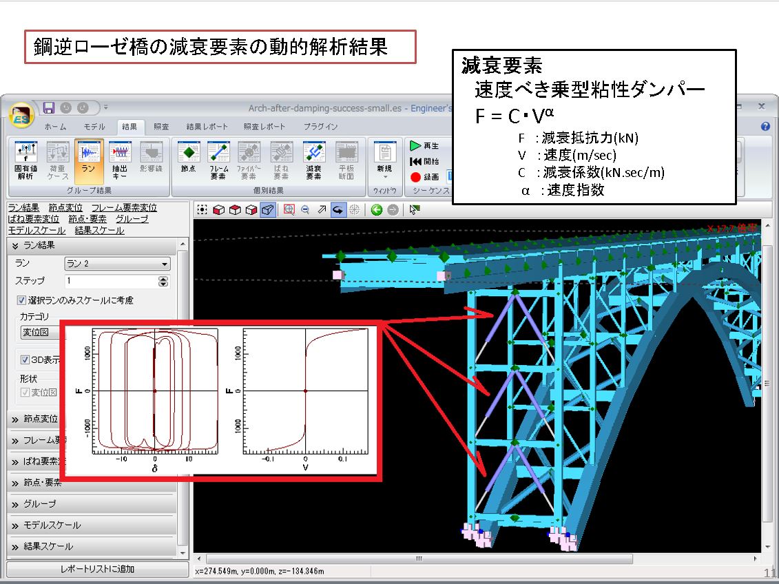
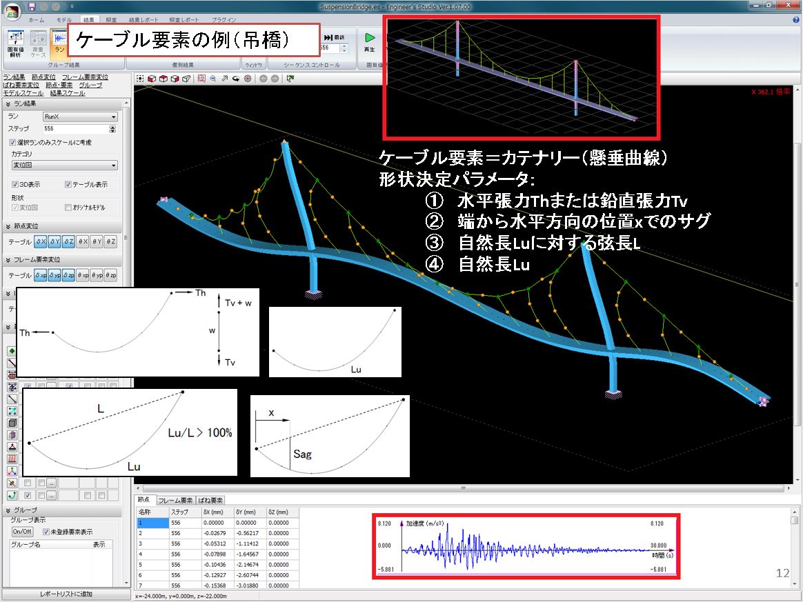
In addition, it also has a plate element based on the Reissner-Mindlin theory, cable element assuming catenary, and speedy damping element.
In addition, the static/dynamic analysis considering geometric nonlinearity corresponding to large displacement is possible as well as the eigen value analysis necessary for the dynamic analysis. Viscous damping such as Rayleigh damping and element-based rigidity proportional damping can also be considered.
As a design support function, Engineer's Studio® can be used for verifications based on some specifications of road bridges and concrete.
This program is available in 32 bit version and 64 bit version. We recommend the 64 bit version for the analysis of large model with many nodes, elements, and analysis steps, as you can use a large amount of memory.

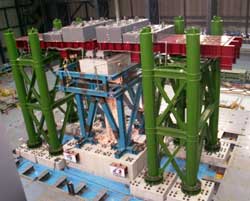
▲Examination of
existing/reinforcement of viaduct

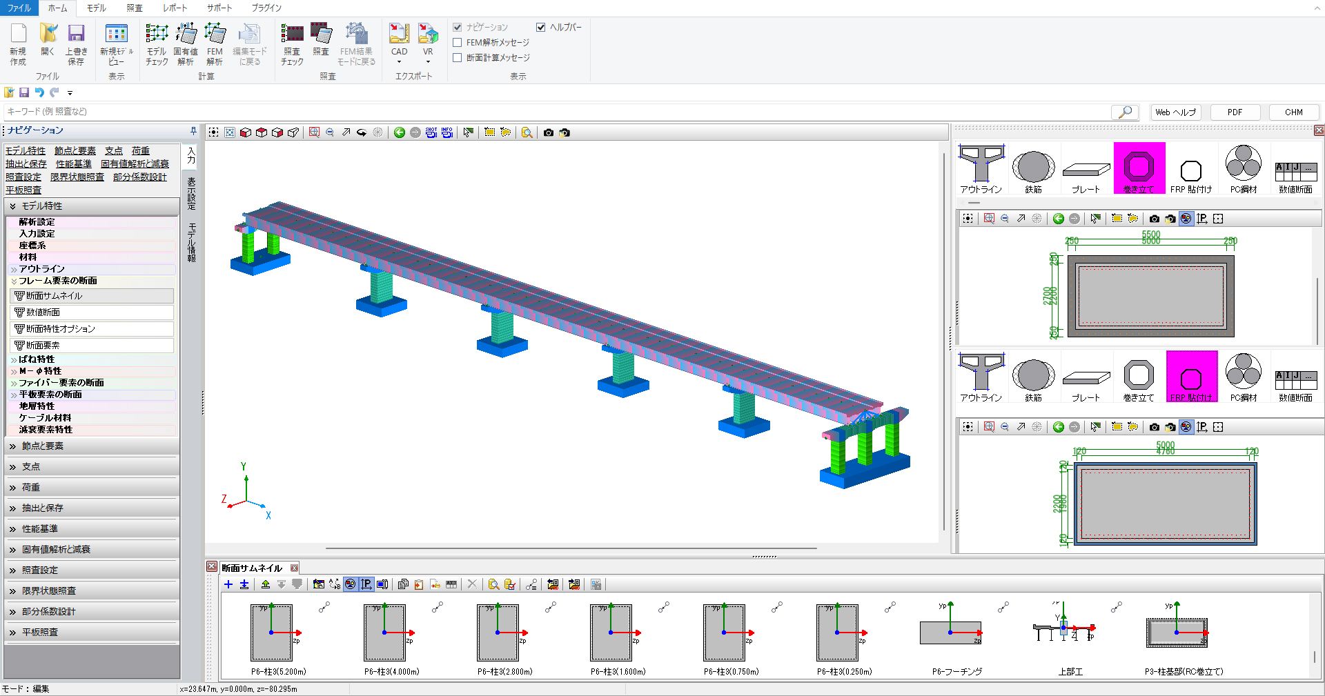
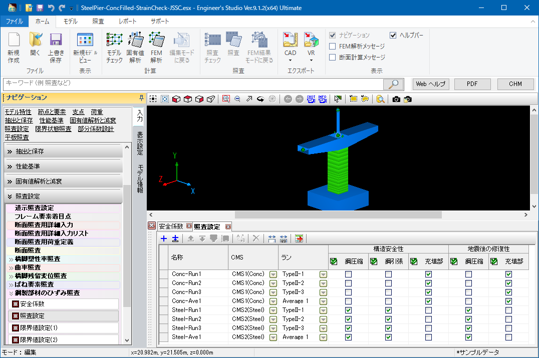
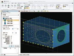
▲Input of section calculation
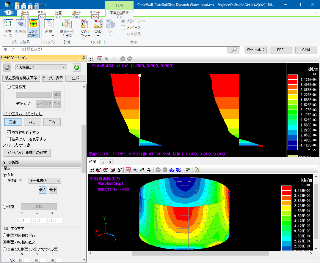
▲3D contour figure and 2D cutting section figure
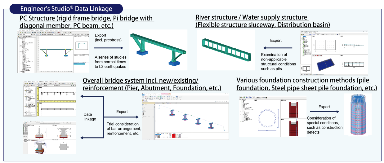
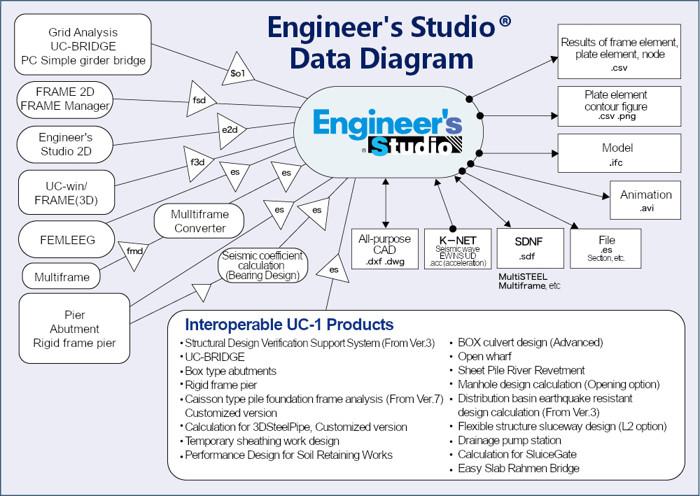
Product / Data Linkage
Product Configuration
| Ultimate | Advanced | Lite | Base | |
| Engineer's Studio Base | ○ | ○ | ○ | ○ |
| Eigen Analysis option | ○ | ○ | - | - |
| Dynamic Analysis Option | ○ | ○ | - | - |
| MPhi Element Option | ○ | ○ | - | - |
| Nonlinear Spring Option | ○ | ○ | - | - |
| Fibre Element Option | ○ | ○ | - | - |
| Geometrical Nonlinear Option | ○ | ○ | - | - |
| Plate Element Option | ○ | ○ | ○ | - |
| Maekawa Concrete Model Option | ○ | - | - | - |
| Beam Model Live Load Option | ○ | ○ | ○ | - |
| Japan Civil Codes Section Design (Old standard) | ○ | ○ | ○ | - |
| Strain Check for Steel Member Option | ○ | ○ | - | - |
| Bridge Residual Displacement Option | ○ | ○ | - | - |
| Cable Element Option | ○ | - | - | - |
| Partial Factors Method Option | ○ | - | - | - |
| Varying Axial Force Option | - | - | - | - |
| Engineer's Studio Section | Included | Included | - | - |
Ver.11.0.0 Revised Contents <Released on August 1st, 2023>NEW
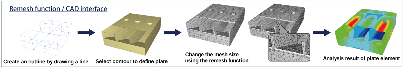
- Remeshing function of flat elements
- Rationalization of eigenvalue analysis and viscous damping
Related Information
- ◆ New Product Information
- Engineer's Studio® Ver.10 (Up&Coming '21 Spring issue)
- Engineer's Studio® Ver.9.1 (Up&Coming '20 Summer issue)
- Engineer's Studio® Ver.9 (Up&Coming '19 Spring issue)
- ◆ Series
- Support Topics / Engineer's Studio®
- ◆ Operation movie
-
5 minutes operation guidance from input to export

-
Arbitrary report setting
- ◆Seminar
- Engineer's Studio®
Functions and Features
Analysis Features
-
Main feature in analysis is that implement the 3D filer elements, which have ever received a good reputation and many actual results in UC-win/FRAME(3D) and the plate elements based on the Reissner-Mindlin theory and also static / dynamic analysis are available, considering material nonlinearity and geometric nonlinearity(Large Displacement) simultaneously.


▲Image of Fiber elements (the mathematical model on the right)
Plate elements can have laminated structures, consists of layers which direct to the thickness way and define each setting for different type of materials between each layers or linear/non/linearity. Reinforcement concrete non linear constitutive equation is adopted as concrete constitutive equation applied to the plate elements, which was developed by the concrete laboratory in Tokyo University. It can be said that this product's plate element has expanded RC element in UC-win / WCOMD to thickness way to multi-layer and has made it possible to analyze non-linear behavior not only of in-plane deformation but also of out-of-plane.
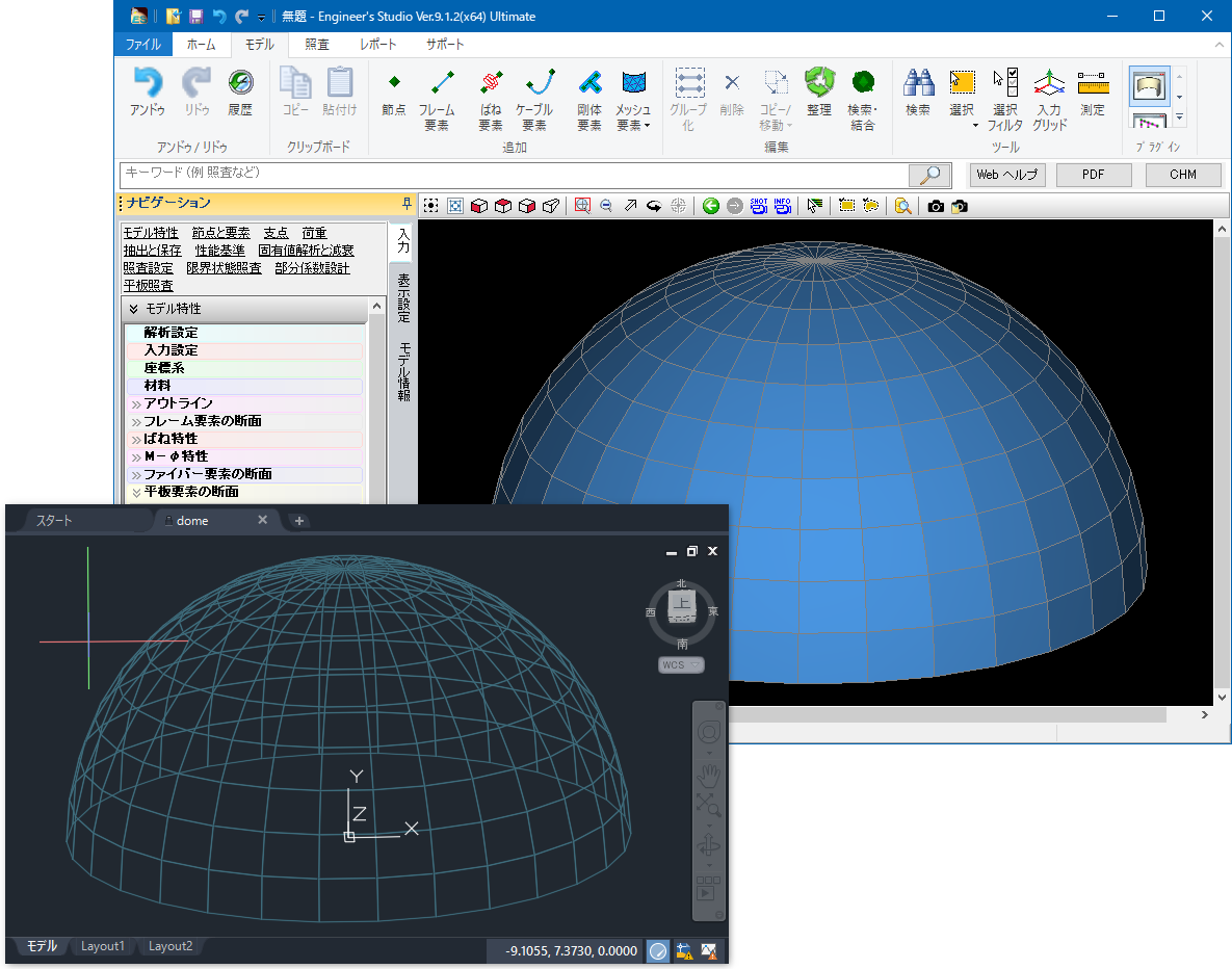
The isoparametric elements that are often used in the FEM have been adopted as flat plate elements.
▲ Image of laminated plate elements (the mathematical model on the right)
Addition of a triangle primary element enables a mixture of 3 and 4 node elements during the automatic mesh of complex shaped field (refer to the Triangular Liner in the figure below). High mesh elements (quadrilateral 8 node element and triangular 6 node element) can be converted into low-elements (quadrilateral 4 node element and triangular 3 node element) after being selected.
・Triangular 3 nodes element and a primary form function
・Triangular 6 node element and a secondary form function
・Quadrilateral 4 node element and a primary form function
・Quadrilateral 8 node element and a secondary form function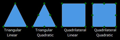
▲Kind of flat plate elements
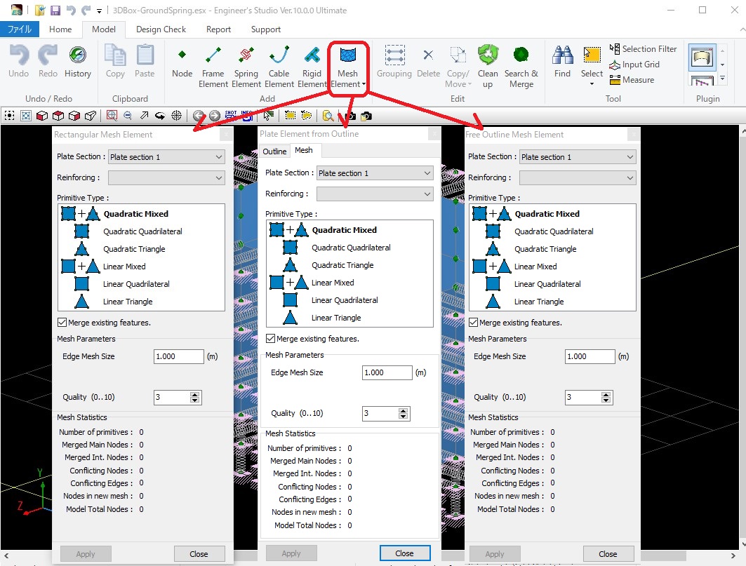
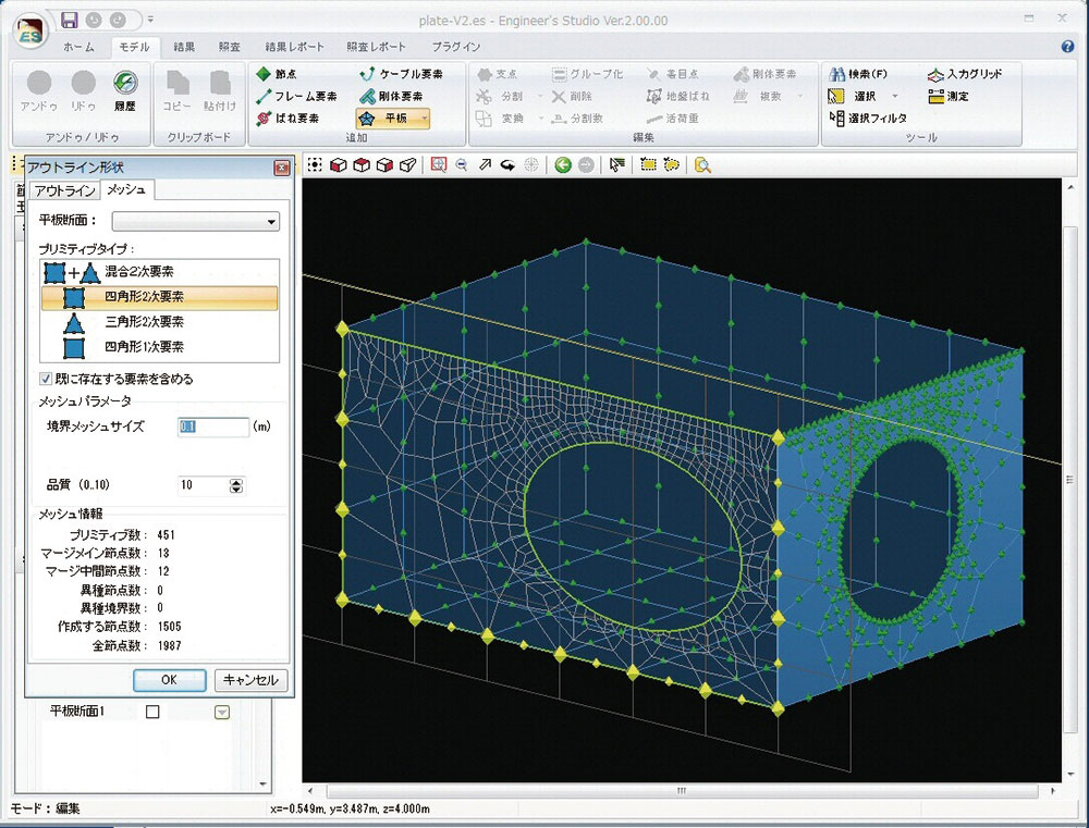
▲Three types of creation commands for plate elements

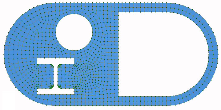
▲Auto-mesh divide with the mixture of square
and triangular primary element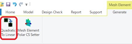
▲The button to convert high-elements into low-elementsThe support of the 64bit version has realized the input and analysis of large models consuming a lot of memory.
You can output a report consisting of many pages (e.g. 30,000 pages).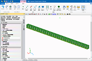
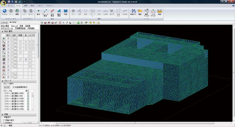
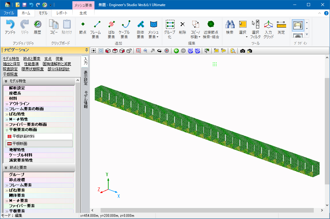
▲Image of a large model
Main analysis functions
-
Category Contents Analysis static analysis / dynamic analysis / eigenvalue analysis / analysis on the influence line of single bar Nonlinear Analysis material nonlinearity / geometric nonlinearity(large displacement) / composite nonlinearity
considering both material nonlinearity and geometric nonlinearity at the same timeApplied Theories infinitesimal displacement / large displacement / elastic foundation beam theory /
Euler-Bernoulli beam theory / Timoshenko beam theory(considering shear deformation) /
Reissner-Mindlin theoryElements elastic beam element / rigid body element / spring element / M-φ element / fiber element /
plate element(laminated plate) / cable element / damping element (Speedy damper)Boundary Conditions locking condition: six degree of freedom for the nodal point(free or fixed or spring) /
distributed spring for elastoplastic beam element (two way of axial member
direction and axial member) / Coupling spring (Defined at node)Material Types concrete / reinforcement bar / PC steel (steel strand wire, steel pipe) /
steel plate / carbon fiber sheet / aramid fiber / elastic material(by input any young module) /
non structural material(considering only weight per unit volume)Definable Load To frame element
nodal load / material load(concentrated / distributed / projection) / thermal load / forced load
To plate element
Flat plate surface load (Distributed load) / Flat plate volume force (Force acting in proportion to mass)
Plate ground displacement (Cylinder tank is the target. Loading of ground response displacement with load)
Flat plate hydrodynamic pressure (Subject to cylindrical water tank. Hausner's approximate expression)
To cable element
Distributed load (Load distributed over cable length) / temperature loadAuto Created Load dead load / prestressed load / horizontal seismic coefficient load Static Load monotone increasing / cyclic (constant, increasing) / reversible cyclic (constant, increasing) Dynamic Load acceleration wave( individual or simultaneous input of two components, vertical adn horizontal) Dynamic Analysis direct integration method by the Newmark-β method(β=1/4) Damping stiffness proportional pattern by element / Rayleigh damping /
Rayleigh damping by element / (initial stiffness, instantaneous stiffness)Mass Matrix Consistent mass matrix / Lumped mass matrix
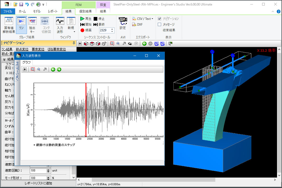
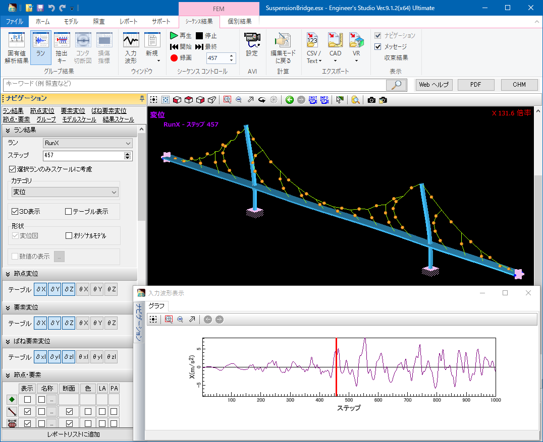
Input waveform is displayed on the result of the dynamic analysis
-
The seismic waveform you entered can be displayed in the new screen when you check the time history results of the dynamic analysis. Click in the graph to move to the next step, and the deformation figure and the section force are synchronized with the step.
▲Entered waveform displayed on the history result
Non linear features
-
Following verifications to RC section compliant with specifications for highway bridges are available; allowable moment stress vrf, moment strength vrf, average shear stress vrf, shear strength vrf, minimum amount of reinforcing bar vrf.
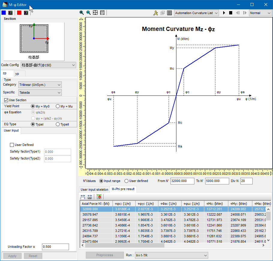
- M-φ feature
-
・Framework: bilinear (symmetric, asymmetric) / tri-linear (symmetric, asymmetric) / tetra linear (symmetric, asymmetric)
・Internal history: Normal / Takeda / elastic / origin-oriented / origin maximum point-oriented / H11 railway seismic
- Spring feature
-
・Framework: bilinear (symmetric, asymmetric) / tri-linear (symmetric, asymmetric) /
tetra linear (symmetric, asymmetric) / Nagoya high-speed rubber bearing type / BMR damper・Internal history: Normal / Takeda / elastic / origin-oriented / origin maximum point-oriented /
H11 railway seismic / positive and negative direction / positive direction / negative direction / shock absorber /
Clough/slip type / Gap/Hook type
- Hysteresis (stress-strain curve for the fiber element)
-
Material Constitutive law Concrete Quadratic curve Models that have been adopted as for the ultimate bending
moment calculation in many compliance standards.Hoshikuma Frameworks are n-dimensional curve and strain softening
straight that takes into account the lateral restrain
effect (specifications for highway bridges). Internal
histories are "F3D original" and "Sakai-Kawashima model".COM3 Constitutive law developed at the concrete laboratory
in University of Tokyo. In reference to JSCE Standard
Specifications for Concrete Structures-2002
(Aseismatic Performance Verification)JSCE The model which simplifies "COM3" type for rod member. Mander Frameworks are fractional functions that takes into
account the lateral restrain effect. Internal histories
are "Sakai - Kawashima model".Reinforcing Bar /
Steel Plate /
PC steelframeworks:
Bilinear (symmetric, asymmetric)
Trilinear (symmetric, asymmetric)Internal histories: kinematic hardening law (straight) / modified
Menegotto-Pinto (Sakai - Kawashima) / modified
Menegotto-Pinto (F8)Carbon Fiber /
Aramid Fiberframeworks:
linear (tensile side only)No internal histories
- Fiber elements
-
Fiber elements(original): Non-linear elements using rigid body link and distributed spring elements. Effects of shear deformation will be ignored. Deformation and rigidity of the member at both ends are independent, and it is suitable to analyze the members that produce negative rigidity. In addition, because of the rigidity matrix based on the constant curvature assumptions up to half of the length of the element, it is also easy to adjust with plastic hinge etc. assumptions that assume curvature constant section such as road bridge.
Fiber elements(primary): Two nodes isoparametric elements using a primary curve for shape function. Based on Timoshenko beam theory, it considers shear deformation effects. Elements curvature distribution in the length direction is constant. Based on the rigidity evaluation on one of the Gauss integration point in the middle of member, it uses Gauss integration and builds rigidity matrix of element.
Fiber elements(secondary): Three nodes isoparametric elements using quadratic curve for shape function.
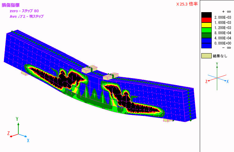
- Convergent improvement and damage index of nonlinear flat plate elements
-
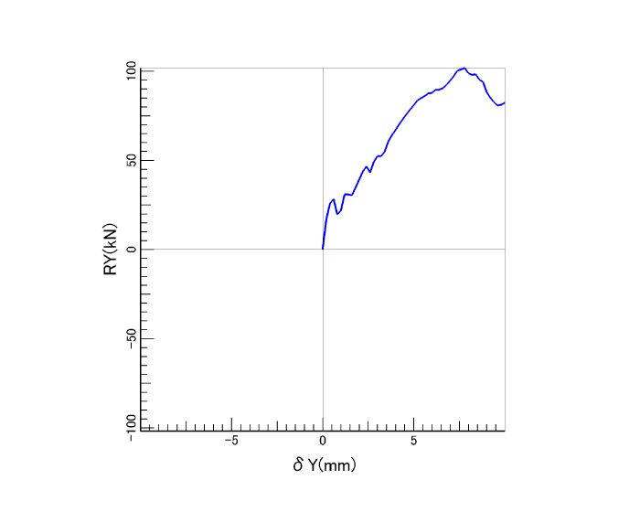
As a verification function for non-linear RC plate element, the program calculates the second invariant of deviation strain and the normalized cumulative strain energy that are the damage index written in "Concrete standard specification (2012, 2017)" by Japan Society of Civil Engineers. Also, the convergence setting for non-linear plate element has been added and the issue that non-linear plate element was not converged easily has been solved. This allows users to reproduce the softening phenomenon that occurs after the maximum peak in the load displacement relationship easier.

▲The second invariant of deviation strain of RC non-linear beam
(average weight)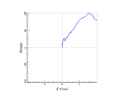
▲Relationship between load and displacement
Design Support
-
・fiber elements, M-φ element, damage display of spring element
・display of damage on M-φ element
・display of damage on spring element
・stress calculation (mainly specifications for highway bridges)
・strength calculation (mainly specifications for highway bridges)
・curvature verification / spring element verification
・function of road bridge residual displacement verification
・ductility factor verification for highway bridges (μ=δmax / δy、μa=δls2 / (α*δy))
・displacement verification of highway bridges
・mport or export of CAD data(DXF / DWG format)
・IFC export
▲Displacement figure contour
▲Slab bending moment contour

Varying Axial Force Option
-
Supports the following functions:
- M-φ element considering axial force variation
- M-θ model (spring element) considering axial force variation
Both are applicable for uniaxial bending but not for biaxial bending. Please use fiber elements for biaxial bending.
▲Enter M-φ element considering axial force variation
Civil Structure Biaxial Section Calculation (Partial Factors Method / Specification for Highway Bridges, 2017) Option
-
Verification by the partial coefficient method adopted in the Specifications for Highway Bridges, 2017.
As a verification for the dynamic analysis of structure, it is possible to perform the shear strength verification and the curvature verification against the maximum response value. Displacement verification and residual displacement verification are available for single column type RC pier and single column type steel pier at every step. In addition, the verification corresponding to the biaxial bending is supported for the displacement verification and residual displacement verification.
Press Release
FORUM8 has released Engineer's Studio® Ver.7. Civil Structure Biaxial Section Calculation (Partial Factors Method / Specifications for Highway Bridges, 2017) Option is added.('17.09.26)

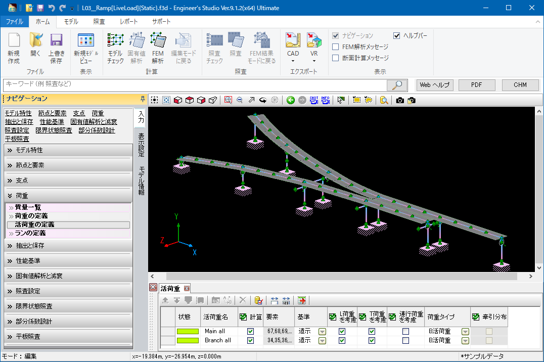
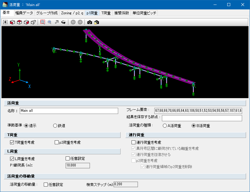
Calculation of live load
-
Live-load calculation is an analysis performed on the influence line of single bar. After creating the influence line, the program searches the location on each target point in which the section force etc. is the greatest or the least by moving the live-load (L load, T load and joint running interval). The analysis is usually for bridge axis.
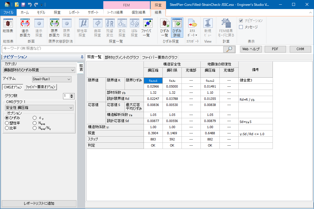
Strain check for steel members
-
Strain check based on the "Standard Specifications for Steel and Composite Structures" (February 2008, Japan Society of Civil Engineers) can be done. By modeling steel members using fiber elements and then assigning safety factors and ultimate strain, the result of strain check can be obtained.
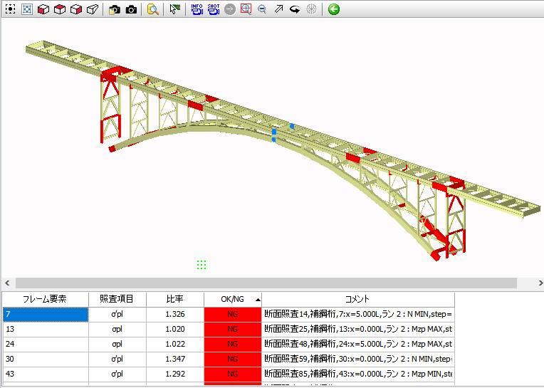
Display NG materials in red
-
Elements (frame / spring) determined as NG in verification can be displayed in red in model drawings.
This function is available for the verification results of section, limit state, curvature, plasticity rate, displacement, residual displacement, and spring.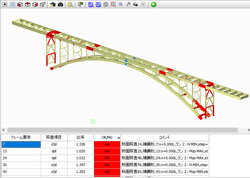
▲NG materials displayed in red
Screen examples
-
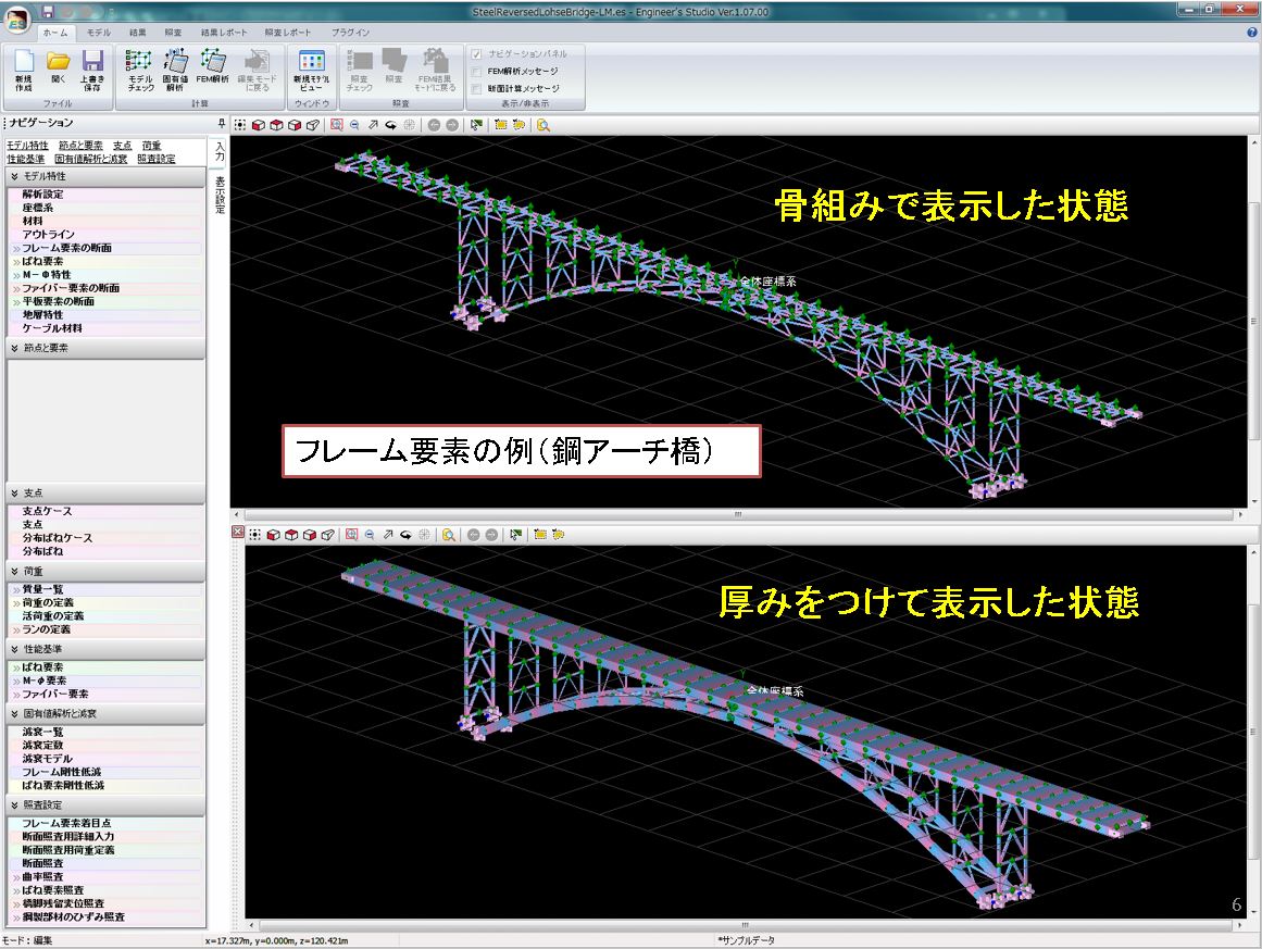
- <Frame element>
-
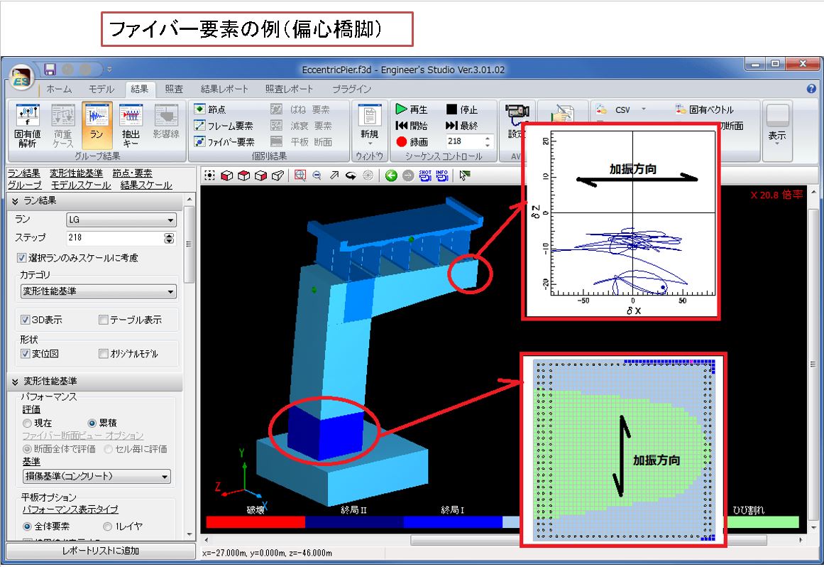
- <Fiber element>
-
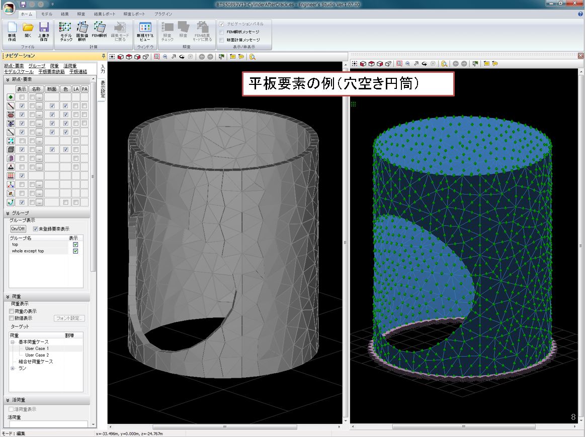
- <Plate element>
-
- <Damping element>
-
- <Cable element>
-
Engineer's Studio® related book
-
Engineer's Studio® Official GuidebookNEW!
■ Author: FORUM8 Analysis Support Group
■ Release: November 2022
■ 304 pages / all color
■ Price: 2,700yen
Move up from beginner to analysis engineer, this is the fastest way to improve your skills! The first official guidebook for Engineer's Studio® is now available!
This book helps beginners in dynamic nonlinear analysis master basic operations from creating models for different purposes to checking results and creating reports. It also includes many frequently used functions, techniques, and use cases. This is a must-have book for performance design engineers.■ Contents
Chapter 1: Basic operations & Interface
Chapter 2: Create models for different purposes
Chapter 3: Check results and create reports
Chapter 4: Technique and advanced functions
Chapter 5: Use cases
Structural analysis with numerical simulation - Learning Nonlinear analysis and response analysis using a software –[Revised Edition]
■ Author: Hiromichi Yoshikawa, Professor Emeritus of Tokyo City University / FORUM8
■ Release: November 18th 2020
■ 235 pages / all color pages
■ Price: 2,800yen
A long-selling book that explains everything from the basics of structural analysis to parametric simulations of actual structures in an easy-to-understand manner has been expanded and renewed. "Technical notes" that summarize the points and precautions of analysis are further enhanced.
■ Contents
Chapter 1: Introduction to structural analysis
Chapter 2: Non linear analysis of section
Chapter 3: Non linear analysis of members
Chapter 4: Earthquake response analysis of structures
Chapter 5: Frame analysis basics
Award
FORUM8 won the Risk Management Design Award
-
Plate cable element compliant Three Dimensional Plate Dynamic Nonlinear Analysis soft "Engineer's Studio®" won the Risk Management Design Award (RiMDA). This award was established by Public Network Institution as the overall design recommended system of the crisis management industry.

▲ Group photo (center: Kawasaki chairman)

▲ Award Ceremony
The 23rd Awards of excellent new technology
and products for small and medium enterprise
FORUM8 won the excellent award!
-
On May 11, 2011, FORUM8's structural analysis software Engineer's Studio® won the excellent award for "The 23rd Awards of excellent new technology and products for small and medium enterprise". This is the advanced structural analysis software for concrete for which FORUM8 and Prof. Koichi Maekawa of Universityof Tokyo have been working together for 25 years. Therefore Prof. Koichi Maekawa also won the award "Special collaboration prize among government, industry and academia".
[Award]
Excellent award for software section, Special collaboration prize among government, industry and academia[Applicant]
FORUM8 Co., Ltd.
Professor Koichi Maekawa, Department of Civil Engineering, Graduate School of the University of Tokyo[Product name]
Structural analysis program "Engineer's Studio®"The NK Industrial Research Institute The 23rd Awards of excellent new technology and products for small and medium enterprise Award winners
https://www.nikkan.co.jp/sanken/shingizyutu/23shingizyutu.html (in Japanese)


FORUM8 won the destruction analysis contest! (2010)
-
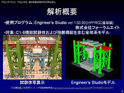
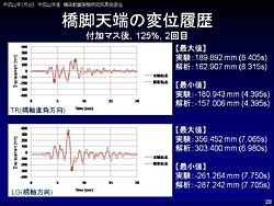
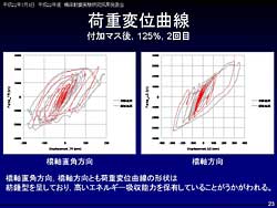
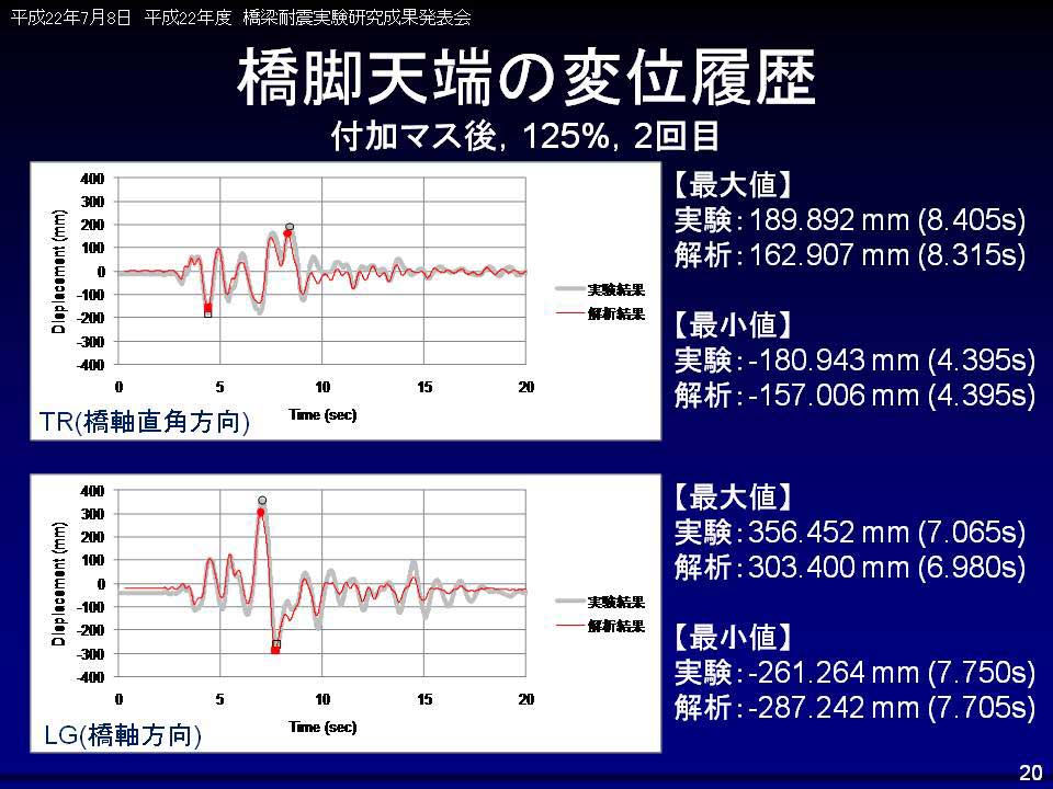
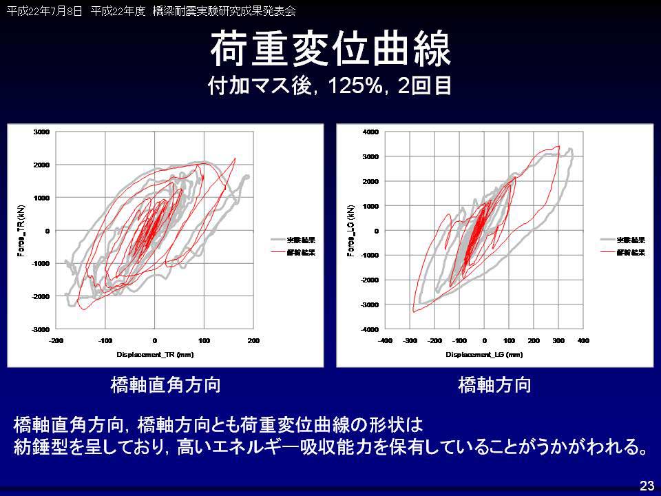
On July 8, 2010, a combined team formed by Forum8 employee (Yoshitaka Kai, Yoichi Matsuyama, Blent Fleming, Keiichiro Abe), president of A-Works, Hirooki Aoto, and Tokyo City University professor, Hiromichi Yoshikawa, were commended as champion of "Destruction analysis and blind analysis contest for seismic resistance experiment on full size bridge made of nature mortar" at the ceremony presenting the results of the 2010 seismic resistance experiment /research on bridge pier, hosted by National Institute for Earth Science and Disaster Prevention in Japan (Independent company). Dynamic nonlinear analysis "Engineer's Studio®"developed by FORUM8 is used for analysis software.
[Press Release (July 8th 2010)]
Engineer's Studio® won Grand Prix at the Destruction Analysis Contest (in Japanese)[Presentation Slide]
・Result for destruction analysis and blind analysis contest for seismic resistance experiment on full size bridge made of nature mortar (PDF, 837KB)

Winner of the pre-analysis contest (2009)
in the fiber model category!
-
On the theme of seismic experiment/research on bridge piers using a full size three dimensional shaking destruction experiment facility (called E-Defense) referred to as "To what extent bridge piers can resist earthquakes?", UC-win/FRAME(3D) analysis support team won the pre-analysis contest in the fiber model category at the ceremony presenting the results for the C1-2 Experiment Pre-analysis Contest for "The 2007/2008 Seismic Resistance Experiment/Research on bridge piers", sponsored by the National Research Institute for Earth Science and Disaster Prevention in Japan, held on the third floor of World Trade Center building on 5 March 2009.
[Press Release (March 6th 2009)]
UC-win/FRAME(3D) analysis support team members won in the fiber model category of the pre-analysis contest (in Japanese)
▲UC-win/FRAME(3D) analysis support team
Development manager, corecipient, Hiroki Aoto
(Second from the right : from Hiromichi Yoshikawa
Lab in Tokyo City University)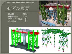
[AVI for analysis result]
[Presentation slide]
・C1-2 Experment Contest Analysis result for fiber model section (Japanese) (PDF, 1,932KB)[Experiment]
・National research Institute for Earth science and Disaster prevent Hyogo EarthqualeEngineering Research Center Website
・Video[Conference presentation]
・9th U.S. National and 10th Canadian Conference on Earthquake Engineering (PDF 1,583KB Tront, Canada in July, 2010)
Price
Product Price
-
■Product Price
Product Name
Price
Engineer's Studio® Ver.11 Ultimate
Product configuration : including Engineer's Studio® Section and all
plug-in options except for "Varying Axial Force option".USD21,000 Engineer's Studio® Ver.11 Ultimate (Not including the Maekawa model)
Product configuration : including Engineer's Studio® Section and all plug-in options except for
"ES-Maekawa Concrete Model Option" and "Varying Axial Force Option".USD14,000 Engineer's Studio® Ver.11 Ultimate (Not including the Cable Element)
Product configuration : including Engineer's Studio® Section and all plug-in options except for
"ES-Cable Element Option" and "Varying Axial Force option".USD16,000 Engineer's Studio® Ver.11 Advanced
Product configuration : including Engineer's Studio® Section and all plug-in options except for
"ES-Maekawa Concrete Model Option", "ES-Cable Element Option",
"ES-Partial Factors Method Option", and "Varying Axial Force option".USD10,000 Engineer's Studio® Ver.11 Lite
Product configuration: "Engineer's Studio® Base" and options below:
・ES-Plate Element Option
・ES-Beam Model Live Load Option
・ES-Japan Civil Codes Section Design (Old standard) OptionUSD5,200 Engineer's Studio® Ver.11 Base
Product configuration : Standard product without optionUSD3,500 ■Price of Floating License
Paying 40% of the product price allows anyone to use the products on any PC anywhere in the world.
Product Name
Price
Engineer's Studio® Ver.11 Ultimate USD8,400 Engineer's Studio® Ver.11 Ultimate (Not including the Maekawa model) USD5,600 Engineer's Studio® Ver.11 Ultimate (Not including the Cable Element) USD6,400 Engineer's Studio® Ver.11 Advanced USD4,000 Engineer's Studio® Ver.11 Lite USD2,080 Engineer's Studio® Ver.11 Base USD1,400
Upgrade
Upgrade Price
-
Program Name Object Product Price/Category Note Engineer's Studio® Ver.11 Ultimate Engineer's Studio® Ver.11 Ultimate
(Not including the Maekawa model)USD8,400 Upgrade - Engineer's Studio® Ver.11 Ultimate Engineer's Studio® Ver.11 Ultimate
(Not including the Cable Element)USD6,000 Upgrade - Engineer's Studio® Ver.11 Ultimate Engineer's Studio® Ver.11 Advanced USD13,200 Upgrade - Engineer's Studio® Ver.11 Ultimate
(Not including the Maekawa model)Engineer's Studio® Ver.11 Advanced USD4,800 Upgrade - Engineer's Studio® Ver.11 Ultimate
(Not including the Cable Element)Engineer's Studio® Ver.11 Advanced USD7,200 Upgrade - Engineer's Studio® Ver.11 Ultimate Engineer's Studio® Ver.11 Lite USD18,960 Upgrade - Engineer's Studio® Ver.11 Ultimate
(Not including the Maekawa model)Engineer's Studio® Ver.11 Lite USD10,560 Upgrade - Engineer's Studio® Ver.11 Ultimate
(Not including the Cable Element)Engineer's Studio® Ver.11 Lite USD12,960 Upgrade - Engineer's Studio® Ver.11 Advanced Engineer's Studio® Ver.11Lite USD5,760 Upgrade - Engineer's Studio® Ver.11 Ultimate Engineer's Studio® Ver.11 Base USD21,000 Upgrade - Engineer's Studio® Ver.11 Ultimate
(Not including the Maekawa model)Engineer's Studio® Ver.11 Base USD12,600 Upgrade - Engineer's Studio® Ver.11 Ultimate
(Not including the Cable Element)Engineer's Studio® Ver.11 Base USD15,000 Upgrade - Engineer's Studio® Ver.11 Advanced Engineer's Studio® Ver.11 Base USD7,800 Upgrade - Engineer's Studio® Ver.11 Lite Engineer's Studio® Ver.11 Base USD2,040 Upgrade - Price of Subscription Service Contract
Price of Subscription Service Contract
-
■Support information
-Software upgrade -Technical inquiry (Email, Tel)
-Download service -Maintenance and update notifications via email
* We are sequentially making a transition from the maintenance-support service to [Subscription Service] from April 1, 2016 in order to enhance support for diverse product usage and to reduce license management cost.
Product Name Subscription cost
of first yearSubscription cost
of subsequent years
(annual cost)Subscription(Engineer's Studio® Ver.11 Ultimate) Free USD8,400 Subscription(Engineer's Studio® Ver.11 Ultimate
(Not including the Maekawa model))USD5,600 Subscription(Engineer's Studio® Ver.11 Ultimate
(Not including the Cable Element))USD6,400 Subscription(Engineer's Studio® Ver.11 Advanced) USD4,000 Subscription(Engineer's Studio® Ver.11 Lite) USD2,080 Subscription(Engineer's Studio® Ver.11 Base) USD1,400 Subscription(Engineer's Studio® Ver.11 Ultimate Floating) USD11,760 Subscription(Engineer's Studio® Ver.11 Ultimate
(Not including the Maekawa model) Floating)USD7,840 Subscription(Engineer's Studio® Ver.11 Ultimate
(Not including the Cable Element) Floating)USD8,960 Subscription(Engineer's Studio® Ver.11 Advanced Floating) USD5,600 Subscription(Engineer's Studio® Ver.11 Lite Floating) USD2,912 Subscription(Engineer's Studio® Ver.11 Base Floating) USD1,960
Price of Rental License / Floating License
■Rental license : Short term licenses available at a low price
■Rental floating license : After web activation, anyone can use the products on any PC anywhere in the world.
■Rental access : You can increase the number of licenses you own and use these additional licenses for a specific period of time (1 month to 3 month) at your discretion. We will later send you an invoice based on your usage log. The advance application is 15% off of the regular rental license price. Please place an order from User information page.
*Rental / Floating Licenses were introduced on September 2007 to enhance user experience and convenience of our products.
*Duration of Rental / Floating Licenses cannot be changed after starting these services. Re-application is required to extend the rental and floating license duration.
Rental license / Rental floating license
-
■Rental License
Product Name 2 month 3 month 6 month Engineer's Studio® Ver.11 Ultimate USD9,240 USD10,920 USD13,440 Engineer's Studio® Ver.11 Ultimate
(Not including the Maekawa model)USD6,300 USD7,420 USD9,100 Engineer's Studio® Ver.11 Ultimate
(Not including the Cable Element)USD7,200 USD8,480 USD10,400 Engineer's Studio® Ver.11 Advanced USD4,500 USD5,300 USD6,500 Engineer's Studio® Ver.11 Lite USD2,340 USD2,756 USD3,380 Engineer's Studio® Ver.11 Base USD1,575 USD1,855 USD2,275 ■Rental Floating License
Product Name 2 month 3 month 6 month Engineer's Studio® Ver.11 Ultimate USD15,540 USD18,480 USD22,680 Engineer's Studio® Ver.11 Ultimate
(Not including the Maekawa model)USD10,500 USD12,460 USD15,400 Engineer's Studio® Ver.11 Ultimate
(Not including the Cable Element)USD12,000 USD14,240 USD17,600 Engineer's Studio® Ver.11 Advanced USD7,500 USD8,900 USD11,000 Engineer's Studio® Ver.11 Lite USD3,900 USD4,628 USD5,720 Engineer's Studio® Ver.11 Base USD2,625 USD3,115 USD3,850 Option price / Product configuration
Option price / Product configuration
-
Option Price Ultimate Ultimate
(not including the
Maekawa model)Ultimate
(not including
the cable model)Advanced Lite Engineer's Studio® Section USD2,800 
- ES-Eigen Analysis option USD200 - ES-Dynamic Analysis Option USD200 - ES-MPhi Element Option USD700 - ES-Nonlinear Spring Option USD700 - ES-Fibre Element Option USD200 - ES-Geometrical Nonlinear Option USD200 - ES-Plate Element Option USD1,100 ES-Maekawa Concrete Model Option USD6,500 - - - ES-Beam Model Live Load Option USD200 ES-Japan Civil Codes Section Design
(Old standard) OptionUSD900 ES-Partial Factors Method Option USD1,400 - - ES-Strain Check for Steel Member Option USD300 - ES-Bridge Residual Displacement USD300 - ES-Cable Element Option USD4,400 - - - ES-Varying Axial Force Option USD1,000 - - - - -
Price of Related Book
Price of Related Book
-
Book Name Price Engineer's Studio® Official Guidebook (in Japanese) USD27.00 STRUCTURAL ANALYSIS -Case Studies and Numerical Simulation (in Japanese) USD28.00
Academic Price
An Academic License can be provided for educational purposes and used by teachers, lecturers, academic researchers, and students.
Academic Price
-
Product Name Academic Price Engineer's Studio® Ver.11 Ultimate USD16,800 Engineer's Studio® Ver.11 Ultimate (Not including the Maekawa model) USD11,200 Engineer's Studio® Ver.11 Ultimate (Not including the Cable Element) USD12,800 Engineer's Studio® Ver.11 Advanced USD8,000 Engineer's Studio® Ver.11 Lite USD4,160 Engineer's Studio® Ver.11 Base USD2,800 Version Upgrade History
Version Upgrade History
-
■The version upgrade and revision upgrade (without charge) contents are listed as following.
Engineer's Studio® Ver.11 Version Released date Update contents 11.0.0 23/08/01 - Remeshing function of flat elements
- Rationalization of eigenvalue analysis and viscous damping
Engineer's Studio® Ver.10 Version Released date Update contents 10.0.0 21/03/31 - M-φ element considering varying axial force
- M-θ model (spring element) considering varying axial force
- * Varying Axial Force Option is required.
Product Operation Environment
Product Operation Environment
-
OS Windows 10 / 11 (64bit OS is recommended)
*The software will work in both of 32 bit OS and 64 bit OS.
It works by OS provided 32bit emulation technology in 64bit OS.
*64 bit version works on the 64 bit OS only, not on the 32 bit OS.CPU Intel® i5-3470,i7-3770, or greater
(Recommended CPU clock 3.2GHz, quad-core is recommended.)Required Memory (including OS) Greater than 4GB RAM is recommended
(varies according to analysis models and analysis steps).Required Disk Capacity Greater than 600 MB for installation, few MB to tens of GB for calculation
(varies according to analysis models and analysis steps)Display (Image Resolution) More than 1280 x 800, colour number 32bit
Please use a default setting for a property of the screen and normal size (96)
for the DPI setting.Videocard OpenGL 3.3 or greater
NVIDIA® GeForce® series with 4GB or more memory
Intel® HD Graphics 4000 series or greaterExtension for Input Data es, esx File Export Only the input data: ES
Data with result: ES + folder
F8 output editing tool is supported by TXT, HTM, PPF, DOC, DOCX, PDF, JTD, JTDCLinkage to Other Products <to read>
Engineer's Studio®2D
UC-win/FRAME(3D)
UC-1/FRAME(2D)
SDNF file (Steel Detailing Neutral File) (SDF)
SI supporting version F8 old product data ($o1)
Acceleration file (text) (ACC)
<to save>
UC-win/Section
SDNF file (Steel Detailing Neutral File) (SDF)Note A card that supports full functionality of OpenGL is required
because OpenGL is used for the 3 dimension graphics processing in this product.Order / Contact Us
Order / Contact Us
-
If you have any question, please feel free to contact us via Sales inquiry or at ist@forum8.co.jp
Samples
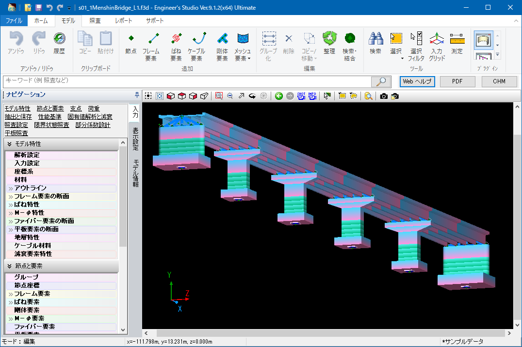
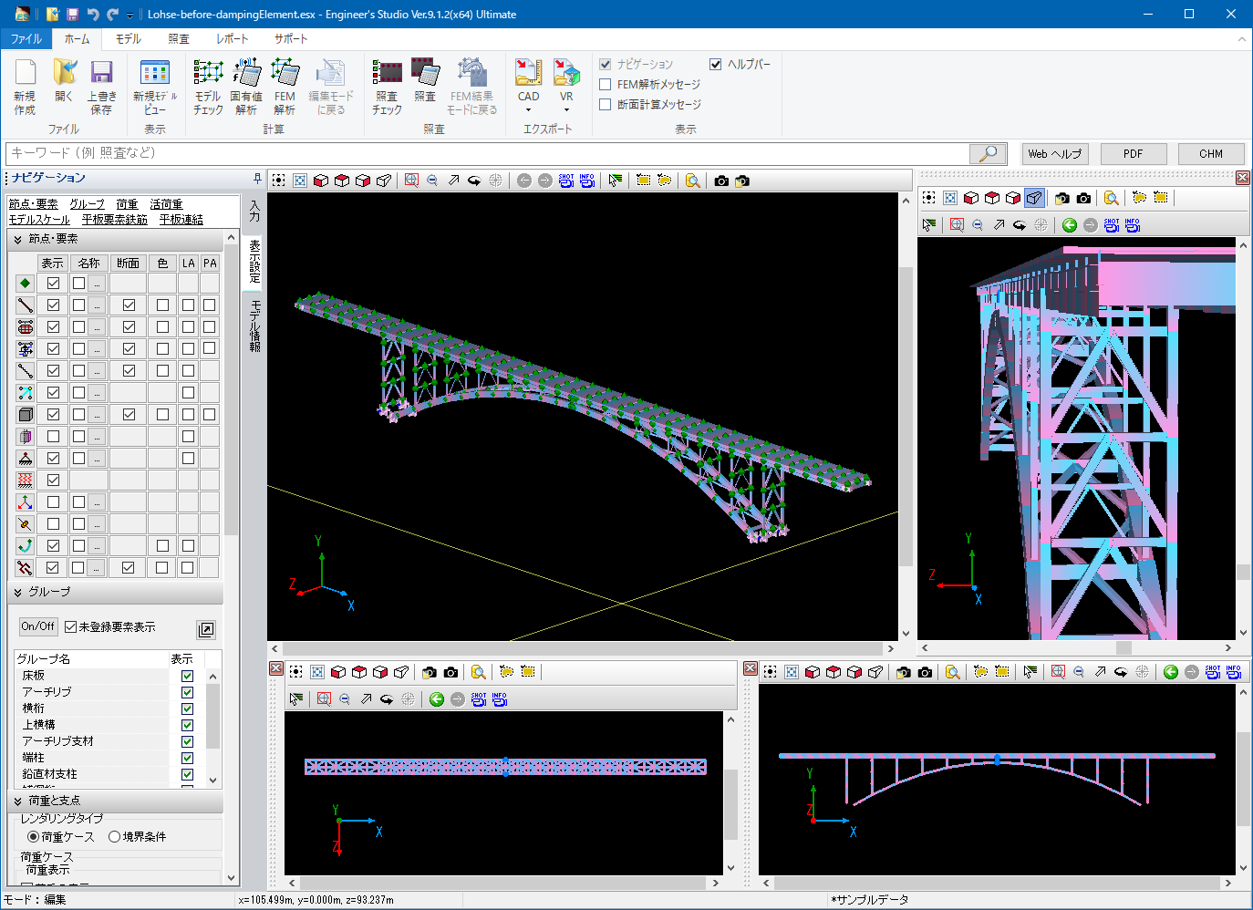
▲ Main window
▲ View setting
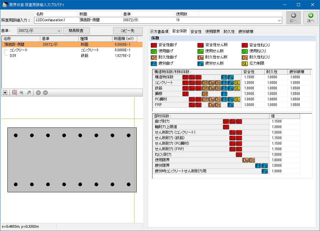
▲ Input of section calculation
▲ 45 thousand nodes model
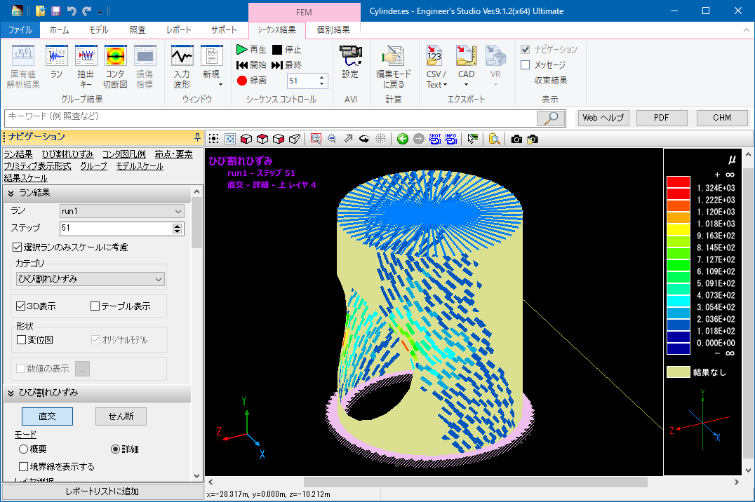
▲ Crack figure of plate element
▲ Auto division of plate element
▲ Contour figure of plate element
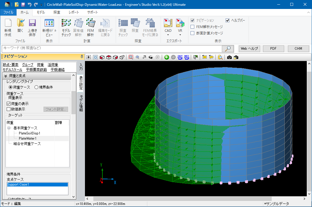
▲ Distributed load to plate element

▲ Auto generation of ground spring on plate element
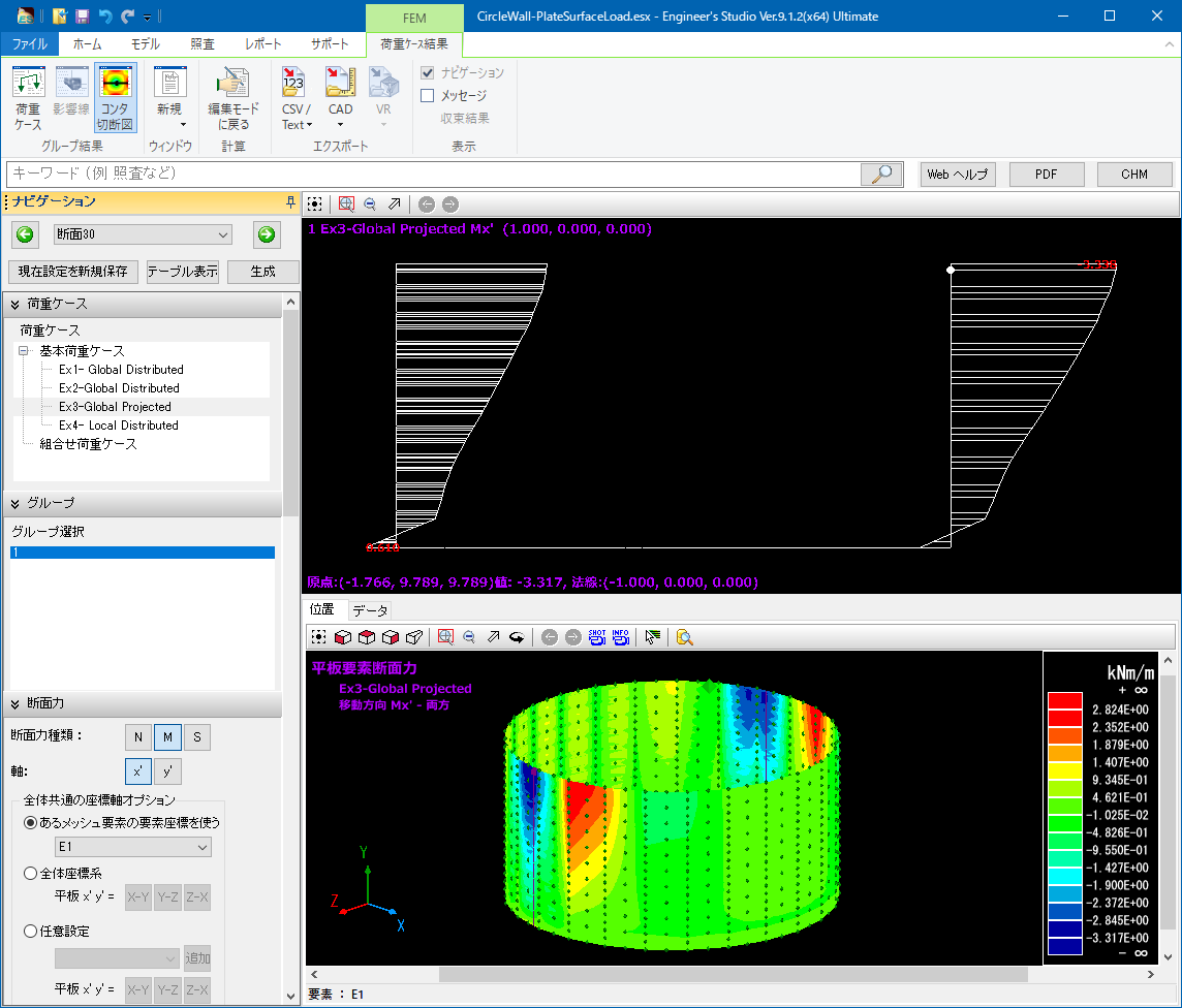
▲3D contour figure and 2D cutting figure
▲ Large displacement analysis of cable element
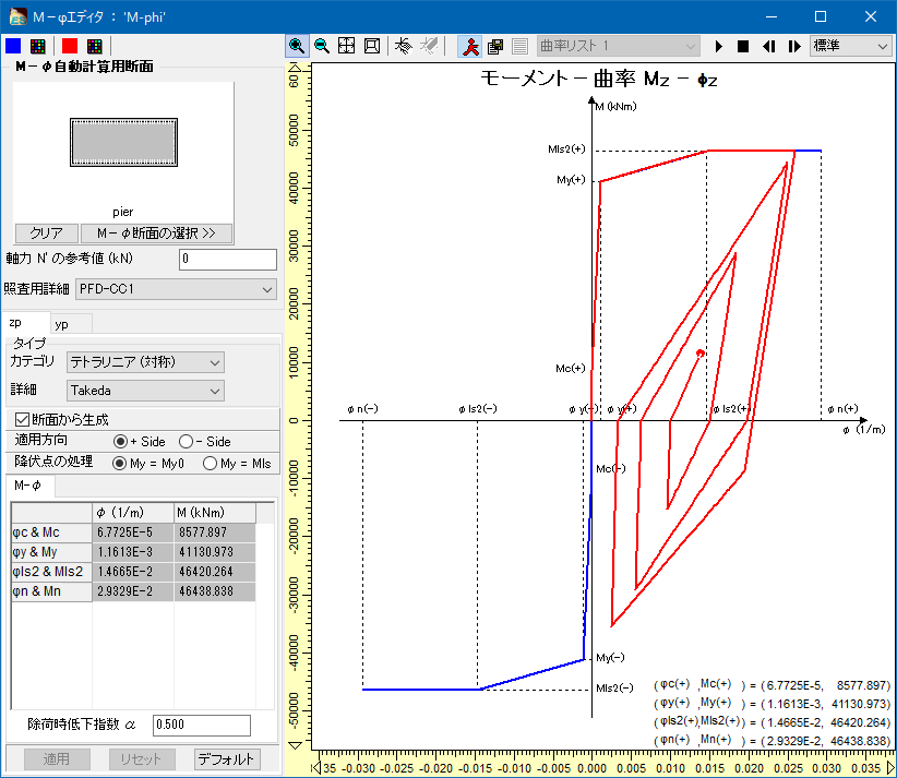
▲ M-φ characteristics linked with the cross section
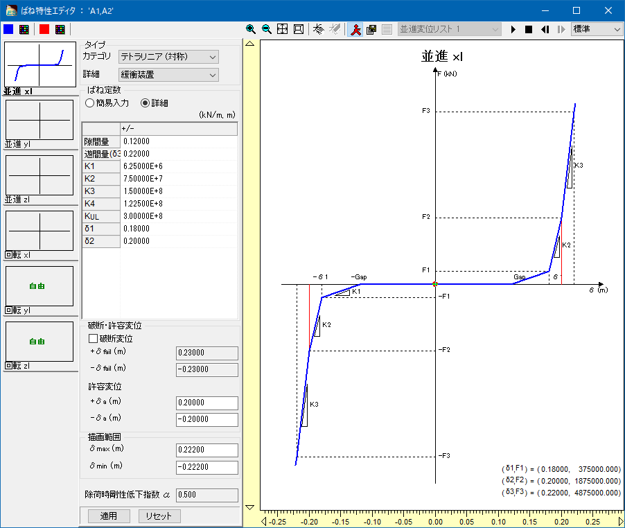
▲ Spring characteristics for shock absorbers
▲ Import/Export in DXF/DWG format
▲IFC export

▲ 2nd invariant volume of deviation distortion of RC non-linear beam
▲ NG materials displayed in red in verification
Q&A
- What can I do with this program?
-
This 3D multi-purpose analysis tool allows you to create from 2D models to 3D frame models.
Also, you can create FEM models using the plate element. Linear element as well as non-linear element can be used for the material, and both of static load and dynamic load are supported.
- For what calculation can I use this program?
-
This program can be used for the static analysis and dynamic analysis of bridges, the seismic calculation and seismic diagnosis of river structures and waterworks, and the calculation of architectural structures.
In addition, as a function that is not supported in other companies' programs, it can automatically generate data which the dynamic analysis can be performed by cooperating with abutment, pier, foundation, and seismic intensity calculation software in the FORUM8's UC-1 design series.
- Can I use results for report?
-
Of course it is possible. However, since the target of analysis is not limited to girder bridges or straight bridges, results is exported at the level of calculation sheet.
You can copy exported results and paste them to the Excel sheets, which is useful for making reports.
- Which standards is the program based on?
-
The program is based on the 2002, 2012, and 2017 Specifications for Highway Bridges used for the bridge design.
As for the section verification, it supports the limited state design method written in the concrete standards specifications, which can be used for the verification of structures.
- What grade program should I buy?
-
We recommend the Lite version for users who mainly perform the linear analysis and static analysis, the Advanced version for those who require the dynamic analysis and non-linear analysis for frame. The Ultimate version is best for those who want to perform the non-linear FEM analysis.
- I have a question about the input.
-
You can refer to the program help and the web manual. We also hold seminars regularly where you can try creating analysis models and ask your questions directly to the lecturer. In addition, we have an optional analysis support service to help creating calculation models, which we contract over 100 works per year.
Analysis Support Service: https://www.forum8.co.jp/product/ucwin/ES/es-analysis-support-service-e-1.html


LOADING