|
Engineer's Studio® 2D is a 2D in plane material and geometrical linear frame/truss
analysis program.
Frame and truss elements can be freely combined in a single model. The
user interface is almost identical to the Engineer's Studio®. The intuitive
CAD style input and editing operations allow users to create and edit models
quickly.
Features of the program
- Creation of continuous beam elements and positioning of nodes (element
resizing), frame elements, spring elements, and rigid body elements (*1)
- Search function (node, frame, spring, rigid body) (*1)
- Displays / hides in group unit. Calculates the max / min bending moment
(*1)
- Automatic creation of dead loadcase and horizontal seismic load
- Calculates material displacement (*1)
- Supporting points can be changed in the selected state. Loads will be kept
even when the element is re-divided. (*1)
- spring element can be connected to the main node of rigid element. Multiple
elements can be connected to rigid element. (*1)
- Moment loads can be input to beam elements supported by distributed springs.
(*1)
- Internal force like prestress can be input to beam elements supported by
distributed springs. (*1)
- UC-1 FRAME (in-plane) (.fsd), (.$o1) data files can be imported.
- Mmax between the focused points of frame element is automatically calculated
against basic loadcase / combined loadcase.
* (*1): These functions are not supported in UC-1 FRAME (in-plane).
 |
 |
 Structure figure of arch bridge model data Structure figure of arch bridge model data
2 screens (dockable) |
Load chart of BOX culvert model data
+ displacement chart image (2 images) |
 |
 |
Displacement figure of
rigid frame bridge model data
+ section force chart |
Tunnel model data structure
+ displacement map |
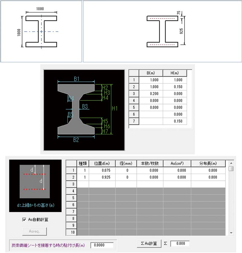
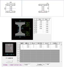
Inputting section shape
Frame calculation can be performed after entering the section shape and
auto-calculating section constant. Supported section shapes: rectangle,
oval, circle, I beam, T beam, W T beam, super structure, super structure
circular hole, block
 |
 |
 |
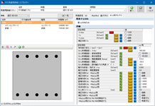
Inputting section shape
and reinforcing bar |
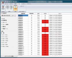
Input screen of section calculation |
List of section calculation result |
Elements
- Euler beam element.
- Truss element (available when both ends are pin in the Element Boundary
Conditions)
- Euler beam on elastic spring element (Defines fixed, free, or spring relationships
between two nodes in each degree of freedom.)
- Rigid body element
Supports
- Node supports.
- Multiple node support cases.
- Multiple spring boundary support cases.
- Support cases are specifiable per load case.
Loading
- Translational and Moment node loading
- Forced node displacements
- Element distributed loading
- Element point loading
- Basic load cases, combinations, and envelopes
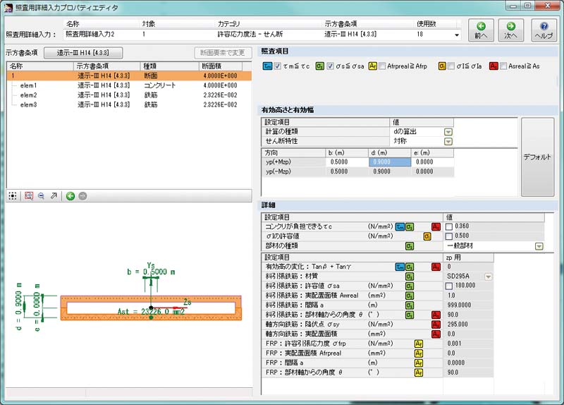
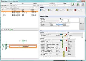
Japan Civil Codes Uniaxial Section Design (Partial Factors method) option
A separately sold option "Japan Civil Codes Uniaxial Section Design
(Partial Factors method)" according to the 2017 Specifications for
highway bridges has been newly added. The bending stress test, bending
strength test, and shear strength test can be conducted by the partial
factors method.
 |
 |
 |
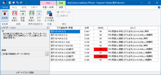
| Entry screen (about shear) |
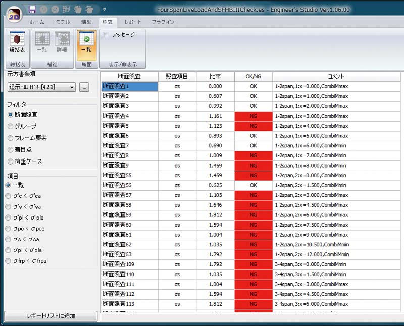
Result screen (summary table) |
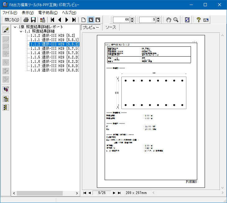
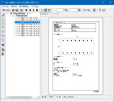
Report export
(result detail) |
|