Stress deformation analysis program of the ground with Finite Element Method
Geotechnical Finite element Elastoplastic Analysis Software(GeoFEAS) 2D Ver.4
Initial Release:2005.12.25 / Latest Ver.:2017.08.01
- Geotechnical Finite element Elastoplastic Analysis Software(GeoFEAS) 2D
- USD6,500
- English Version
- USD13,000
Related products and services:
Geotechnical analysis support service
Program Overview
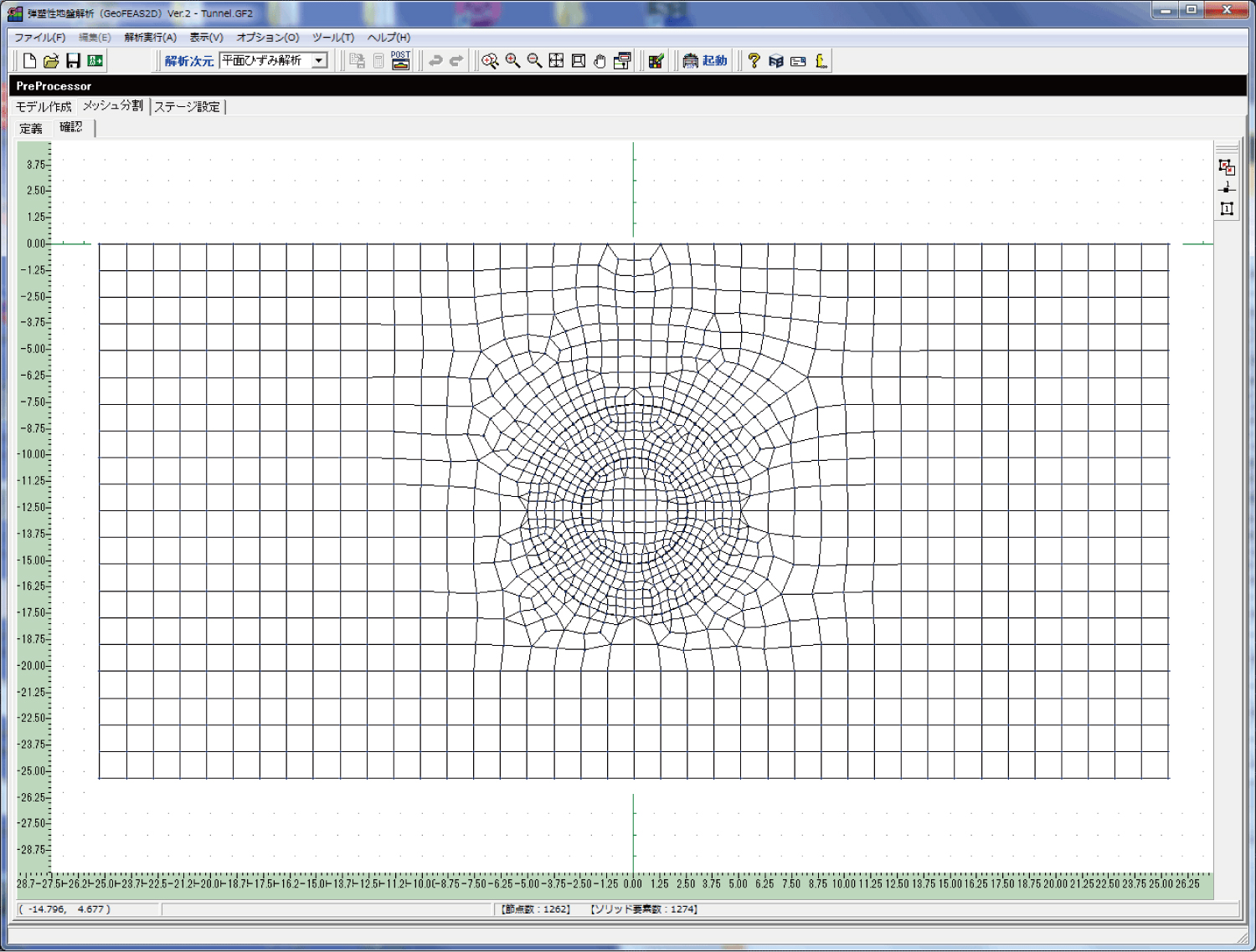
GeoFEAS 2D is `2D Geotechnical Finite element Elastoplastic Analysis Software´. It is the software product for stress-deformation analysis of soil under static conditions. This software conducts the powerful elasto-plastic finite element analysis in many engineering fields such as slope stability analysis, earth retaining works excavation analysis, shield tunnel design, etc. This is a 2D PrePost version for plane strain analysis and axisymmetric analysis. FEM model can easily be created with the CAD-like input method. It also supports import from SXF file.
FORUM8 and Ukai laboratory have been engaged in joint development. The solver of this product utilizes the ground analysis program developed by Ukai laboratory, Department of Civil and Environmental Engineering of Gunma University and the Pre-Post processor is developed in-house and then coupled together as a total solution.
▲Tunnel excavation analysis
Preprocessor
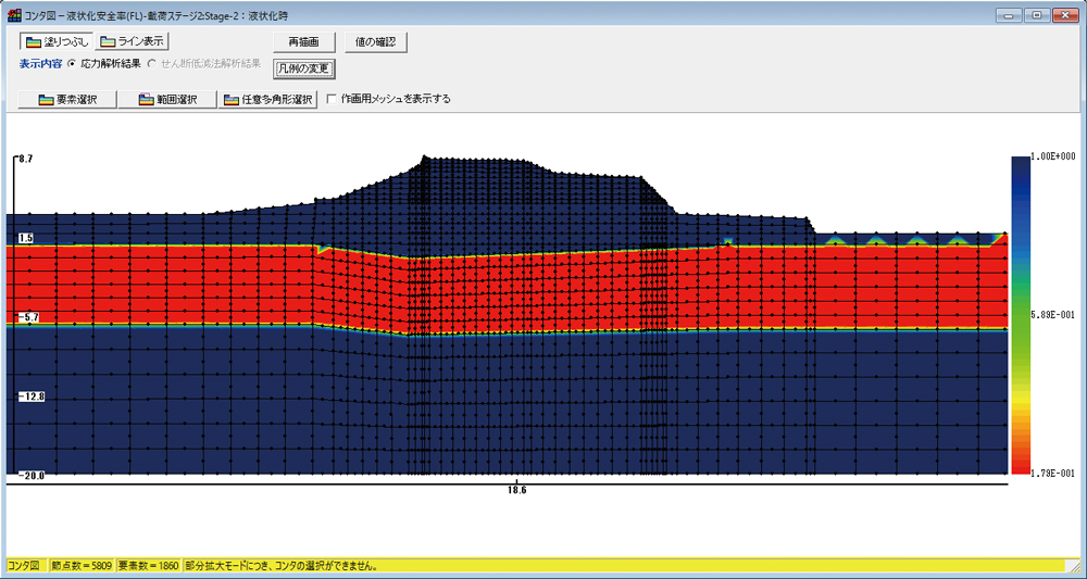
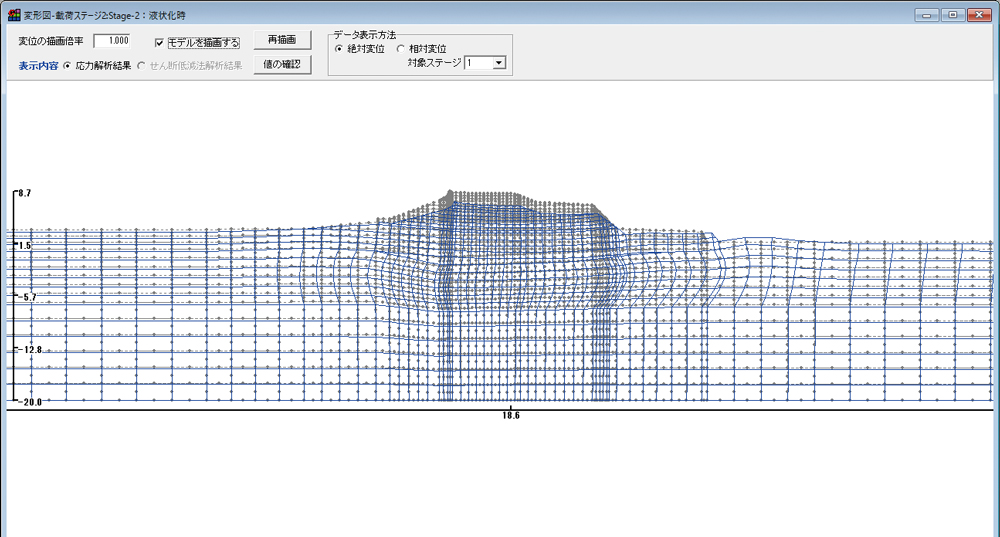
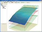
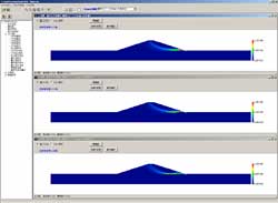
▲Self-weight deformation analysis of river bank during earthquake
(Deformation figure, FL figure)
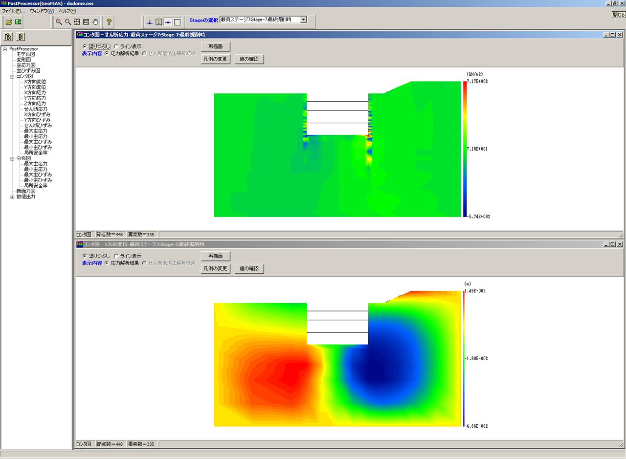
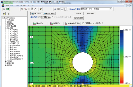
▲Temporary sheathing work analysis
(X-axis contour figure)
Related Information
- ◆New Product Information
- Geotechnical Finite element Elastoplastic Analysis Software(GeoFEAS) 2D Ver.4 (Up&Coming’17 Spring issue)
- ◆Paper / Presentation
- FORUM8 Design Festival 2012
- The 6th Design Conference Report of Special Lecture (Up&Coming’13 New Year issue)
Functions and Features
Analysis method
-
Analysis category
Static total-stress analysis
Analysis models
Plane strain analysis, Axisymmetric analysis
Main features
-
Stage analysis
The stage analysis, or the phased construction analysis can be performed.
It is possible to change material parameters, boundary conditions, and stress release factors for excavation at each stage.
Shear strength reduction (SSR) analysis
It is possible to evaluate global safety factor and slip surface by SSR analysis at each stage.
The shear strength reduction (SSR) analysis can be performed using three kinds of elastic-perfectly plastic constitutive laws.
Local factor of safety
It is possible to calculate the local safety factors at each Gaussian point.
Coordination with seepage analysis
It is possible to use nodal water pressure loads from seepage analysis (Note: This is for the analysis using load module).
Combination of stage and SSR analyses
It is possible to perform both deformation and stability analyses at the same time by combining stage and SSR analyses, and to deal with a wide range of soil related problems such as filled/excavated area, slope stability, bearing capacity, etc.
Mixed assignment of constitutive laws
It is possible to assign different constitutive laws for each material.
2007 Guidelines for Quake-Resistance Testing of River Structures
Deformation analysis: Before liquefaction, Under liquefaction, Volume compression after liquefaction
2016 Guidelines for Quake-Resistance Testing of River Structures
Soil liquefaction analysis based on the March 2016 Edition of " Guidelines for Quake-Resistance Testing of River" established by River Improvement and Management Division, Water and Disaster Management Bureau, Japan Ministry of Land, Infrastructure, Transport and Tourism is feasible. "Deformation analysis prior to an earthquake (before liquefaction)", "Deformation analysis after an earthquake (after liquefaction)", and "Amount of land subsidence (deformation analysis) caused by bulk compression of liquefaction layer" can all be assigned to each stage of the analysis for a very thorough analysis.
Self-weight induced deformation analysis involves deformation analysis before an earthquake (before liquefaction)" and deformation analysis after an earthquake (after liquefaction), and then taking the difference of the results from each analysis to compute the amount of land subsidence caused by liquefaction. The amount of land subsidence (deformation analysis) caused by the bulk compression of the liquefaction layer is calculated separately to the deforamtion analysis before and after an earthquake. By adding the value for the amount of land subsidence caused by the bulk compression of the liquefaction layer to the value for the amount of land subsidence caused by liquefaction, the overall displacement of the model of interest can be determined.
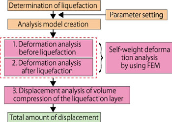
Work flow of deformation analysis
Boundary conditions
-
- Supporting point (horizontal and vertical rollers, fixed, pin, enforced displacement)
- Multi point constraint (MPC)
- Spring supporting point
- Pin connection
Element libraries
-
○=Supported, ×=Not supported
Category Element 2D Axisym-metric Note Line Beam First order element ○ - Bar First order element ○ - Axial spring ○ - Including spring supporting point Shear spring ○ - Including spring supporting point Torsion spring × - Distributed axial spring × - Distributed shear spring × - Surface Three-node triangle ○ ○ First order element for 2D & axisymmetric analyses Four-node quadrilateral ○ ○ First order element for 2D & axisymmetric analyses Six-node triangle ○ ○ Second order element for 2D & axisymmetric analyses Eight-node quadrilateral ○ ○ Second order element for 2D & axisymmetric analyses Joint Four-node line joint ○ ○ Apply between 2D first order elements Six-node line joint ○ ○ Apply between 2D second order elements
Constitutive law models
-
Constitutive law models for elements in plane strain and axisymmetric analyses
It is possible to use 4 elastic models (including 2 bilinear elastic models), 1 nonlinear elastic model, 3 nonlinear models, 3 elastic-perfectly plastic models, and 2 elasto-plastic models. The elastic models can be used as No-Tension materials.
Category Constitutive law Note Elastic Linear elasticity Isotropic Laminated elasticity Anisotropic Shear stiffness reduction material 1 2007 Guidelines for Quake-Resistance Testing of River Structures /
2016 Guidelines for Quake-Resistance Testing of River StructuresShear stiffness reduction material 2 2007 Guidelines for Quake-Resistance Testing of River Structures /
2016 Guidelines for Quake-Resistance Testing of River StructuresNonlinear elastic D-min Technique by CRIEPI Nonlinear HD (Hardin-Drnevich) RO (Ramberg-Osgood) UW-Clay (Ugai-Wakai) Elastic-perfectly plastic MC (Mohr-Coulomb) Associative/nonassociative flow rule DP (Drucker-Prager) Associative/nonassociative flow rule MC-DP (Mohr-Coulomb / Drucker-Prager) Nonassociative flow rule Elasto-plastic PZ-Sand (Pastor-Zienkiewicz) PZ-Clay (Pastor-Zienkiewicz) No-Tension Linear elasticity Laminated elasticity Bilinear Liquefied material 1 2007 Guidelines for Quake-Resistance Testing of River Structures Liquefied material 2 2016 Guidelines for Quake-Resistance Testing of River Structures
Constitutive law models for beam, bar, spring, and joint elements
It is possible to use the following constitutive law models for beam, bar, spring, and joint elements.
Element Constitutive law Support Note Beam M-φ 1. Linear elasticity ○ 2. Bilinear × 3. Trilinear × Bar 1. Linear elasticity ○ 2. Bilinear ○ 3. Trilinear × Spring 1. Linear elasticity ○ Including spring supporting point 2. Bilinear ○ Including spring supporting point 3. Trilinear × Joint 1. Linear elasticity ○ 2. MC (Mohr-Coulomb elastic-perfectly plasticity) ○
Loads
-
- Concentrated load: Nodal force load (2D, axisymmetric)
- Uniformly distributed load, distributed load: Linear distributed load (2D, axisymmetric)
- Self weight load: Vertical acceleration (2D, axisymmetric)
- Seismic inertia load: Horizontal response acceleration (2D), Vertical response acceleration (2D)
- Nodal water pressure load (2D, axisymmetric)
GeoFEAS2D can consider effects of water pressure change on soil by taking into account water pressure as nodal load.
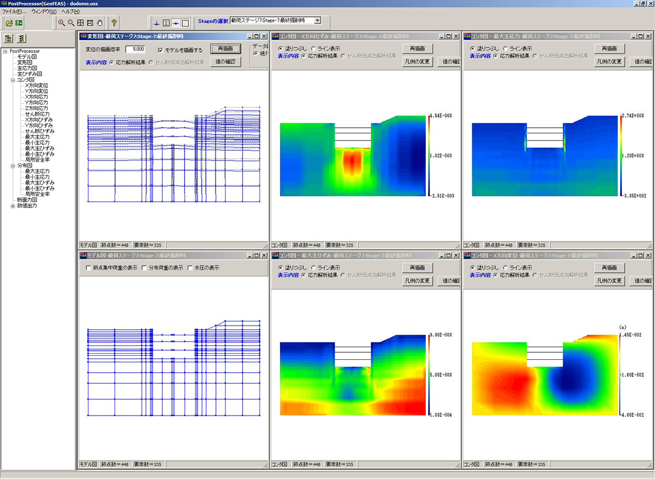
Postprocessor
-
- Model figure
- Deformation figure
- Vector diagram
- Contour figure
- Distribution map
- Numeric output
Output analysis of processor (Analysis section) is processed. Output / confirmation of result figures and numerical values are carried out. In this program, the following can be output mainly.
Cooperation with the UC-1 Earth retaining work design (Option)
-
In Earth Retaining Work Design 3DCAD, it allows examining the effect to surrounding ground by "enforcement displacement method" which works vertical overburden pressure on the bottom of excavation if needed, giving the FEM analysis model that modeled only ground to the displacement of earth retaining wall from elastoplastic analysis as enforced displacement.
▲Elastoplastic result of
earth retaining work
▲Earth retaining work FEM
(Input screen of the forced
displacement method)
▲Earth retaining work FEM
(Contour figure of the forced
displacement method)
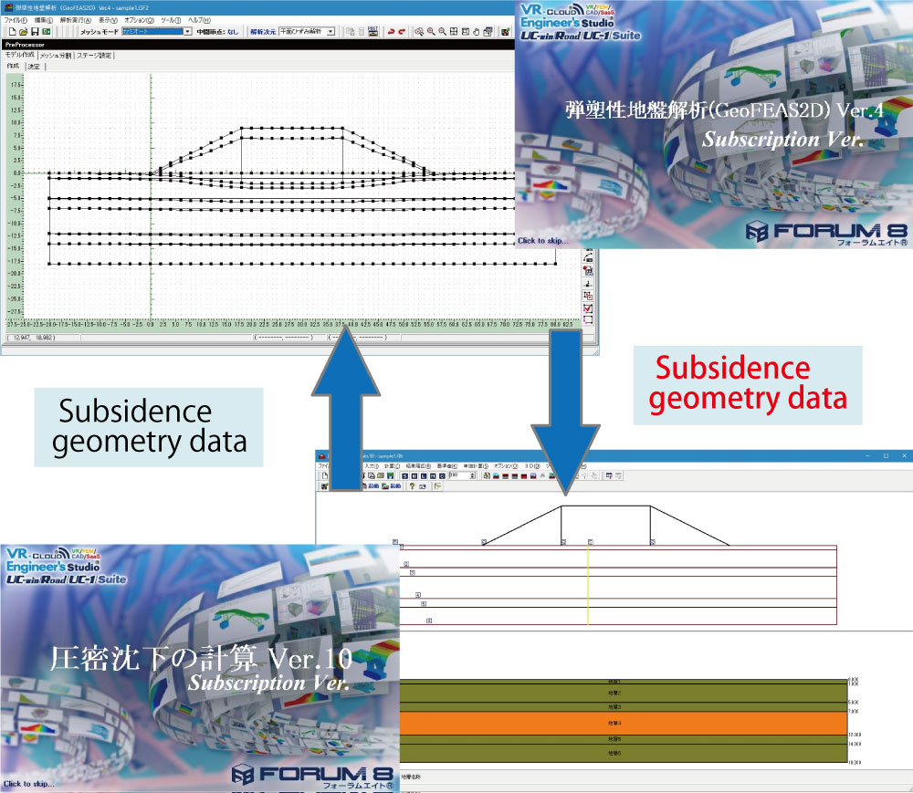
Cooperation with UC-1 Consolidation settlement calculation
-
The new and improved version of GeoFEAS2D can be linked with "Consolidation Settlement Calculation", another popular UC-1 Series product, to take into account consolidation due to compression (consolidation settlement and immediate settlement) when performing liquefaction analysis. Consolidation Settlement Calculation program allows users to set up a complete scenario of consolidation settlement from the creation of soil geometry and assignment of soil layers and vertical load to the calculation of the settlment due to consolidation. The soil model created with its soil geometry and soil layers defined, and subjected to vertical load for consolidation settlement calculation using Consolidation Settlement Calculation program can be imported to GeoFEAS2D for a seamless soil liquefaction analysis.
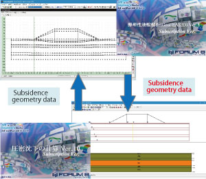
▲Flow of compressive deformation analysis of ground
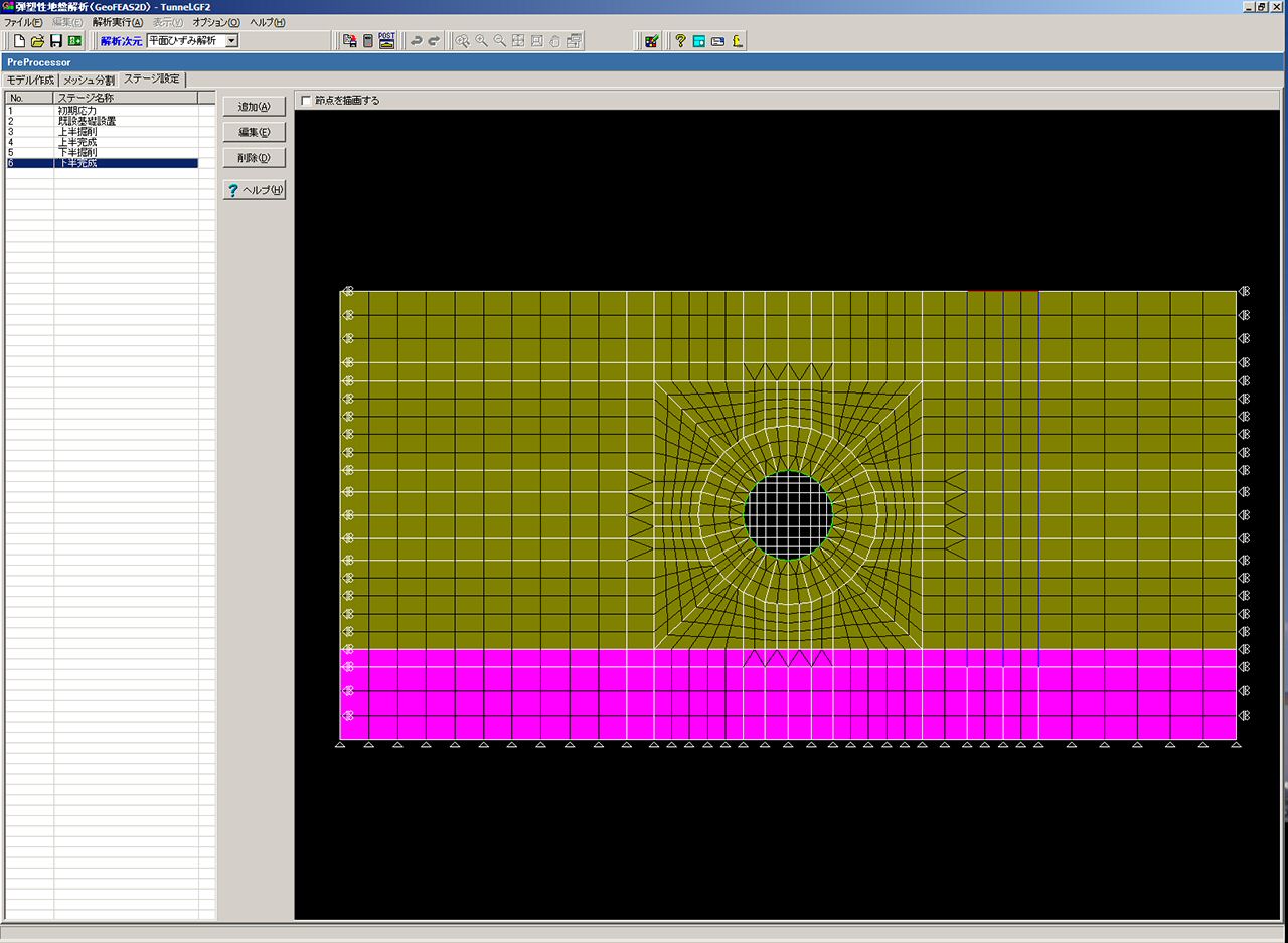
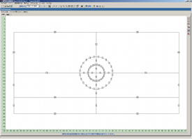
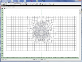
Auto mesh function
-
In case of model creation of like tunnel, mesh division by defining minimum required lines such as stratum boundary reduces the time of model creation.

Applicable scope
-
- Stress-deformation analysis of soil
- Slope stability analysis
- Earth retaining works excavation analysis
- Analysis of surrounding soil effect by shield tunnel construction
- ATM tunnel construction analysis
- Study of water pressure variation effect on soil
- Study of soil-structure interaction
- Ground response acceleration method
Enhancement of CIM function on the geotechnical analysis series products
-
We enhanced the CIM (Construction Information Modeling) function of various products in the geotechnical analysis series. The programs can cooperate terrain data or data created with each geotechnical analysis programs smoothly.
Data linkage using terrain data file (*.GF1) Geotechnical Finite element Elastoplastic Analysis Software(GeoFEAS)2D Ver.4
The amount of displacement exported to Flexible structure sluiceway design for further analysis
By importing results of ground deformation analysis (settlement / horizontal displacement distribution) into the "Flexible structure sluiceway design", the level2 seismic test for the longitudinal direction can be performed.

It can model only ground that a surrounding ground effect analysis is conducted in the Temporary sheathing work design. The ground deformation can be calculated by giving the wall displacement as the forced displacement.Dynamic effective stress analysis for ground(UWLC)Ver.2
Acceleration rate exported to Slope stability analysis for further analysis
When applying the Newmark method to high embankments with a height of about 30 m or more, it is necessary to input the response acceleration waveform of the slip soil mass as the ground motion.
Data linkage between "Dynamic effective stress analysis for ground (UWLC)" and "Slope stability analysis" corresponds to the Newmark method analysis calculated by using the response acceleration waveform.
The level2 seismic stability calculation for high embankment and large embankment.
2-D seepage analysis(VGFlow2D) Ver.3
Water line data exported to GeoFEAS2D
Water level data exported to UWLC
Water line and potential line exported to Slope stability analysis
Saturated / unsaturated seepage FEM analysis results can be reflected by file linkage (*.PRS [water line], *.PTN [isopotential line]).GeoFEAS Flow3D (limited to the seepage analysis)
Water level data imported to LEM3D
Analysis results computed with GeoFEAS Flow3D (limited to the seepage analysis) or third party's product can be imported to 3-D slope stability analysis(LEM). It creates underground water level required for landslide analysis and enables the 3D slope stability analysis.


Application criteria and References
- Applied Standard
-
Guidelines for
Quake-Resistance Testing2007 Guidelines for Quake-Resistance Testing of River Structures
2016 Guidelines for Quake-Resistance Testing of River Structures ll. Levee ed
- References
-
- Potts, D., Axelsson, K., Grande, L., Schweiger, H. and Long M. : Guidelines for the use of advanced numerical analysis, Thomas Telford, 2002
- 鹿島建設土木設計本部編:新・土木設計の要点(5),トンネル,鹿島出版会,2003
- 田中忠治,鵜飼恵三,河邑眞,阪上最一,大津宏康:地盤の三次元弾塑性有限要素法,丸善,1996.
- Zienkiewicz, O.C., Chan, A.H.C., Pastor, M., Schrefler, B.A. and Shiomi, S.: Computational Geomechanics with Special Reference to Earthquake Engineering, JOHN WILEY & SONS, 1999.
- 後藤學:実践有限要素法,大変形弾塑性解析,コロナ社,1995
- マトリックスと有限要素法[改定新版] (O.C. Zienkiewicz, R.L.Taylor, Kagaku Gijutsu Shuppan, Inc.), 1996
Price
Product Price
-
■Product Price
Product
Price
Geotechnical Finite element Elastoplastic Analysis Software(GeoFEAS) 2D Ver.4 USD6,500 Geotechnical Finite element Elastoplastic Analysis Software(GeoFEAS) 2D (English Version) USD13,000 ■Price of Floating License
Paying 40% of the product price allows anyone to use the product on any PC anywhere in the world.
Product
Price
Geotechnical Finite element Elastoplastic Analysis Software(GeoFEAS) 2D Ver.4 USD2,600 Geotechnical Finite element Elastoplastic Analysis Software(GeoFEAS) 2D (English Version) USD5,200
Price of Subscription Service Contract
Price of Subscription Service Contract
-
■Support information
-Software upgrade -Technical inquiry (Email, Tel)
-Download service -Maintenance and update notifications via email
* We are sequentially making a transition from the maintenance-support service to [Subscription Service] from April 1, 2016 in order to enhance support for diverse product usage and to reduce license management cost.
Product Subscription cost
of first yearSubscription cost
of subsequent years
(annual cost)Subscription (Geotechnical Finite element Elastoplastic Analysis Software
(GeoFEAS) 2D Ver.4)Free USD2,600 Subscription (Geotechnical Finite element Elastoplastic Analysis Software
(GeoFEAS) 2D(English Version))USD5,200 Subscription (Geotechnical Finite element Elastoplastic Analysis Software
(GeoFEAS) 2D Ver.4 Floating)USD3,640 Subscription (Geotechnical Finite element Elastoplastic Analysis Software
(GeoFEAS) 2D(English Version) Floating)USD7,280
Price of Rental License / Floating License
■Rental license : Short term licenses available at a low price
■Rental floating license : After web activation, anyone can use the products on any PC anywhere in the world.
■Rental access : You can increase the number of licenses you own and use these additional licenses for a specific period of time (1 month to 3 month) at your discretion. We will later send you an invoice based on your usage log. The advance application is 15% off of the regular rental license price. Please place an order from User information page.
*Rental / Floating Licenses were introduced on September 2007 to enhance user experience and convenience of our products.
*Duration of Rental / Floating Licenses cannot be changed after starting these services. Re-application is required to extend the rental and floating license duration.
Rental license / Rental floating license
-
■Rental License
Product 2 month 3 month 6 month Geotechnical Finite element Elastoplastic Analysis Software
(GeoFEAS) 2D Ver.4USD2,925 USD3,445 USD4,225 Geotechnical Finite element Elastoplastic Analysis Software
(GeoFEAS) 2D(English Version)USD5,850 USD6,890 USD8,450 ■Rental Floating License
Product 2 month 3 month 6 month Geotechnical Finite element Elastoplastic Analysis Software
(GeoFEAS) 2D Ver.4USD4,875 USD5,785 USD7,150 Geotechnical Finite element Elastoplastic Analysis Software
(GeoFEAS) 2D(English Version)USD9,750 USD11,570 USD14,300 Academic Price
An Academic License can be provided for educational purposes and used by teachers, lecturers, academic researchers, and students.
Academic Price
-
Product Academic Price Geotechnical Finite element Elastoplastic Analysis Software(GeoFEAS) 2D Ver.4 USD2,170 Geotechnical Finite element Elastoplastic Analysis Software(GeoFEAS) 2D(English Version) USD4,340 Version Update History
Version Update History
-
■The version upgrade and revision upgrade (without charge) contents are listed as following.
Geotechnical Finite element Elastoplastic Analysis Software(GeoFEAS) 2D English Version Version Release date Update contents 1.01.00 07/05/30 - The stage setup screen operations such as element definitions, analysis conditions, and water pressure settings in the Pre section have been made faster.
- In the Pre section, nodes can be added on the water level line.
- In the Pre section, added control for cases where the total release ratio exceeds 1.0 on the input screen for the stress release ratio.
- In the Pre section, a new "rectangle selection (box enclosure) mode" is available to select only the area enclosed by a rectangle.
- Coordinate axis display is now supported in the Pre section.
- Added a button to register regular polygons in the Pre part model creation.
- The number of nodes and elements are now displayed in the Pre section.
- Product help is now available in HTML format (for Vista).
Product Operation Environment
Product Operation Environment
-
OS Windows 10 / 11 CPU Environments that meet the system requirement of the OS and operate without any problems. Memory (including OS) Environments that meet the system requirement of the OS and operate without any problems. Disk capacity 120MB or more. Analysis requires 500MB to a few GB depending on model size. Display (image resolution) 1024×768 or greater Extension for input data GF2 File export No. Refer to the help manual for the analysis output file. Linkage to other products <to import>
Drawing (SXF、DXF)
Geotechnical analysis data (USD)
Terrain data for geotechnical analysis (GF1)
<Linkage>
Temporary sheathing work design 3D CAD
Flexible structure sluiceway design 3D bar arrangement
Dynamic effective stress analysis for ground (UWLC)
Consolidation settlement calculation
Order / Contact Us
Order / Contact Us
-
■ Inquiry
Contact us from Sales inquiry or email to ist@forum8.co.jp or forum8@forum8.co.jp
Sample
▲Tunnel excavation analysis:
pre-processor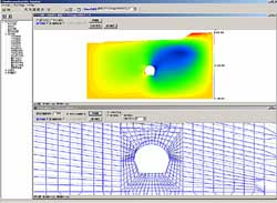
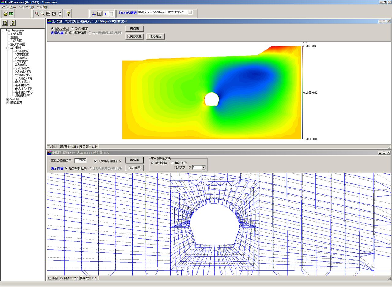
Tunnel excavation analysis result
post-processor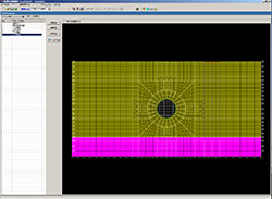
▲Tunnel excavation analysis
(Element definition figure)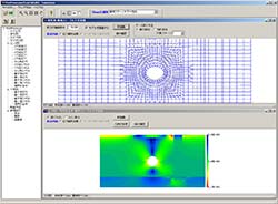
▲Tunnel excavation analysis result
(Deformation figure)
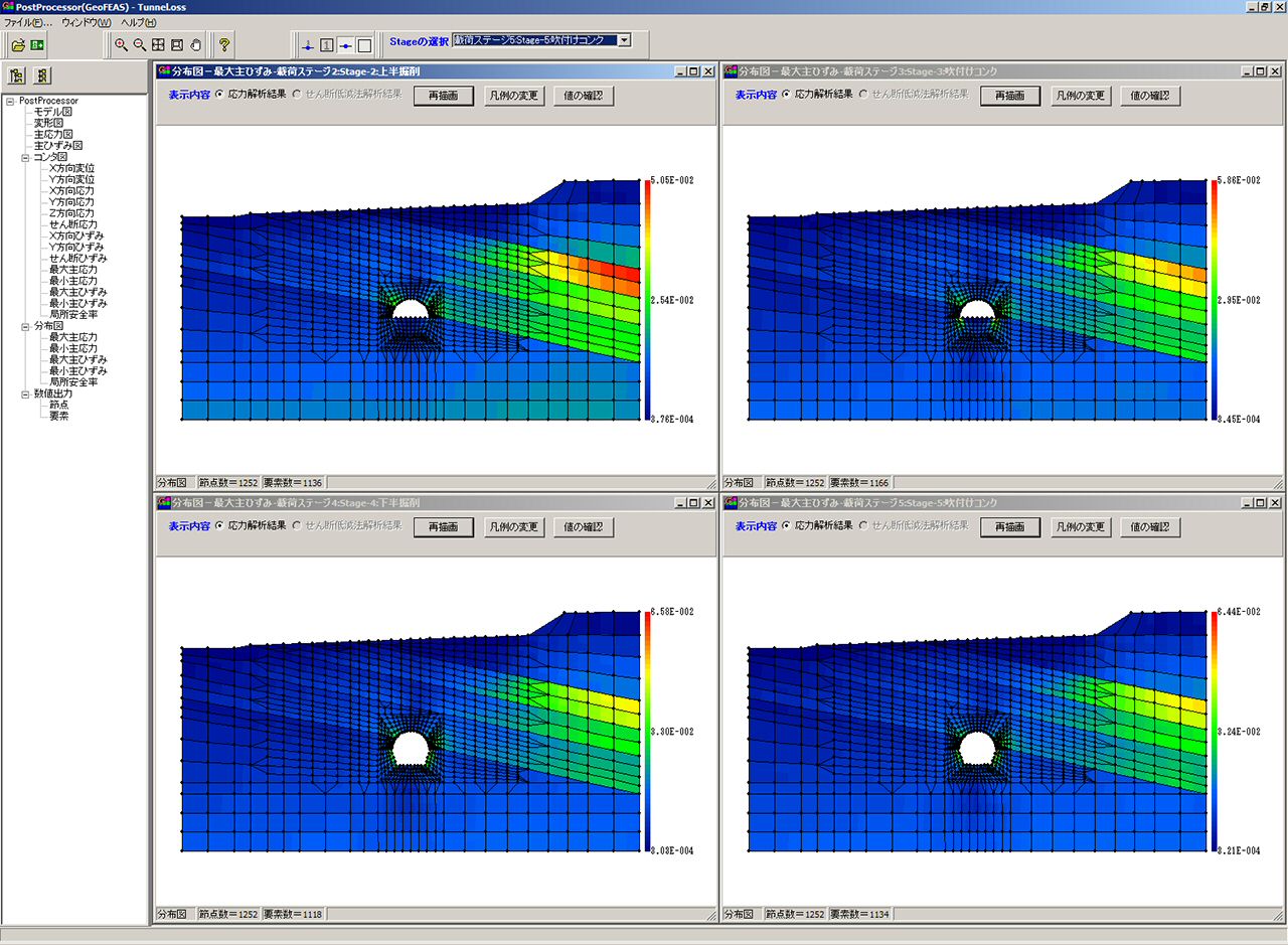
▲Tunnel excavation analysis result
(Maximum distortion)
▲Tunnel excavation analysis result
(Checking the numerical data of elements)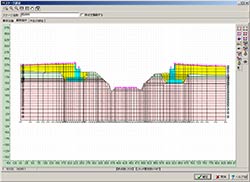
▲Impact analysis of bridge over railway
(Model figure)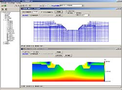
▲Impact analysis of bridge over railway
(Deformation figure)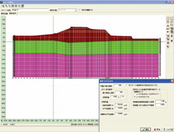
▲Self-weight deformation analysis of river bank during earthquake
(Model figure)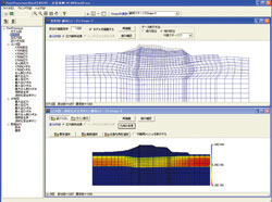
▲Self-weight deformation analysis of river bank during earthquake
(Deformation figure, FL figure)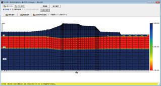
▲Result of liquefaction safety factor (FL)
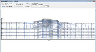
▲Results of deformation due to liquefaction
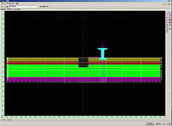
▲Earth retaining excavating analysis
Preprocessor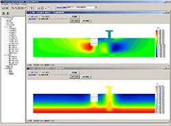
▲Earth retaining excavating analysis result
(Contour figure of an X direction)
▲Earth retaining excavating analysis
Postprocessor
▲Earth retaining excavating analysis result
(Contour figure of an X direction)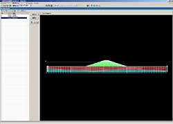
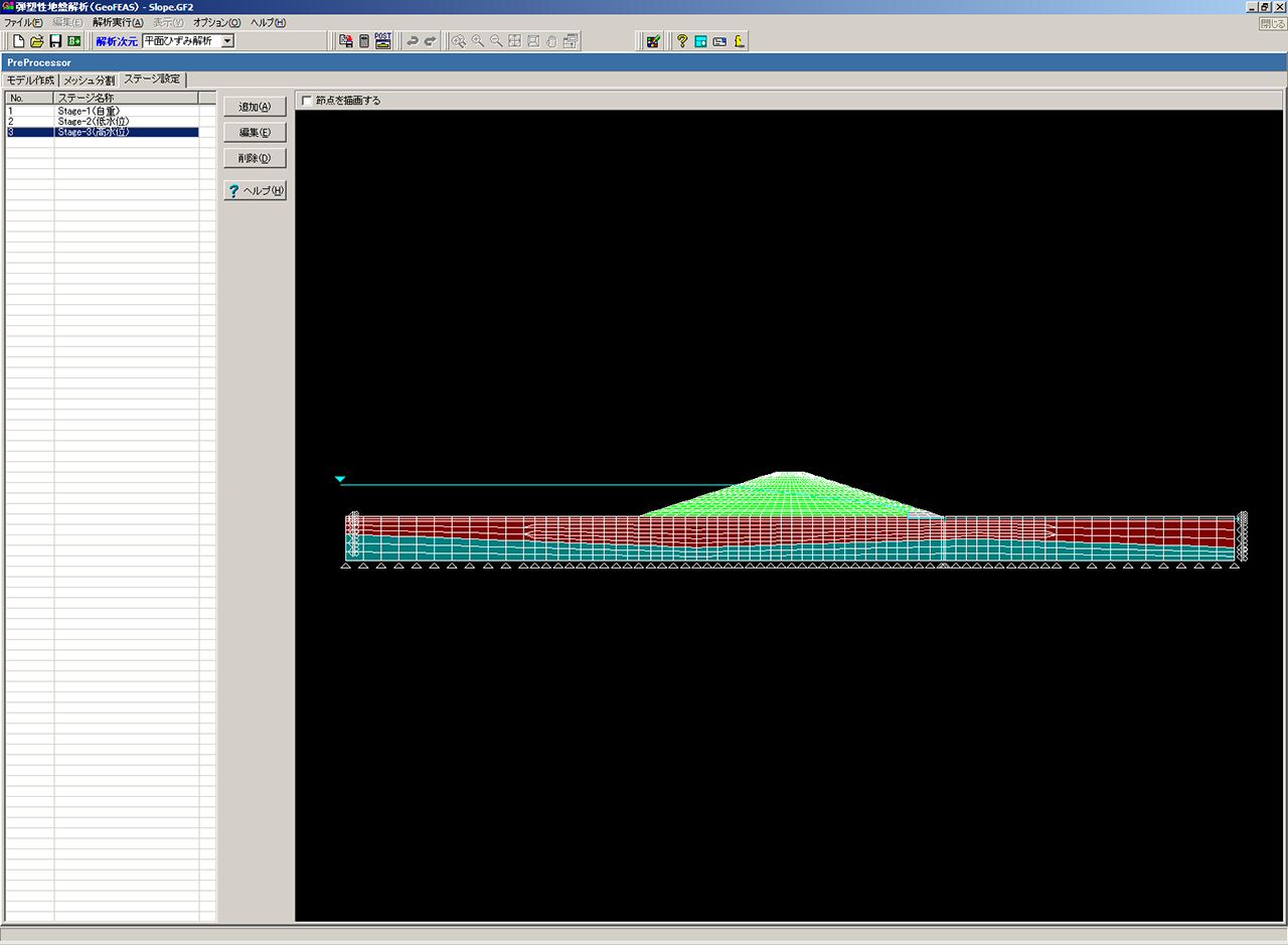
▲Slope stability analysis-Preprocessor
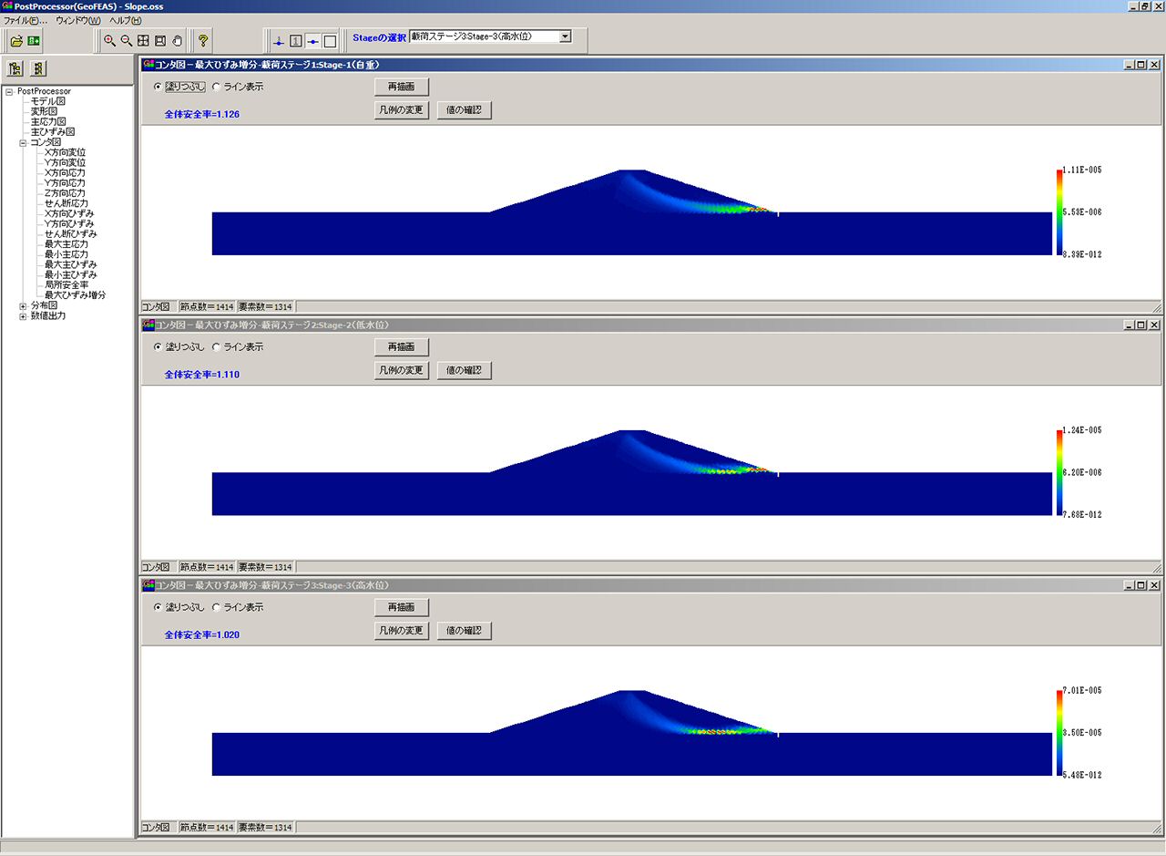
▲Slope stability analysis-Postprocessor
▲Local safety factor contour figure
1.機能・概要
- トンネル掘削による周辺地盤の変形解析において「掘削解放率」の設定はできるか?
また、併設トンネルの掘削で、先行トンネルの「掘削解放率」が100%未満の状態で後行トンネルの掘削を入力することはできるか? -
掘削解放率の設定は可能です。例えば、
- Stage1で自重計算
- Stage2で先行トンネルを掘削する。
この先行トンネルの解放率を40%、次のStage3で残りの60%に設定。 - Stage3で後行トンネルを掘削する。
この後行トンネルの解放率を100%に設定。
というような段階施工検討ができます。
本プログラムでは、[ステージ設定]ウィンドウの[要素定義]タブの右側に並んでいるボタン群の一番下から2番目に[応力解放率の設定]ボタンがありますので、そちらより設定していただけます。 - 「Geotechnical Finite element Elastoplastic Analysis Software(GeoFEAS)2D」の斜面の安定解析と「斜面の安定計算」の違いについて教えてほしい。
-
「Geotechnical Finite element Elastoplastic Analysis Software(GeoFEAS)2D」の斜面の安定解析は、せん断強度低減法のオプションを選択して弾塑性解析を行い、プログラム内の計算上でせん断強度を少しずつ低減していく過程で、斜面内に大きなせん断ひずみが発生するので、その面(画面上では線として見ます)をすべり面とし、その時に低減した割合を全体安全率とする解析です。したがって、有限要素解析のモデルですべり面と安全率を求めることができます。
一方、「斜面の安定計算」では、極限平衡理論をもとに力の釣り合いだけで、円弧により仮想的に設けたすべり面に対して安定計算をし、仮定したすべり円について安全率の計算を繰り返し、最終的に最小安全率となるすべり円を求める計算となります。 既往の研究では両者の結果がほぼ一致するとの報告があります。 - 粘性土で圧密沈下が生じ側方変位が予想される。橋台に対する影響を解析したいが、どのような土のモデル(構成則)を用いたらよいか。
-
圧密計算を有限要素解析で理論的に行う場合にはCam Clayモデルや関口太田モデルが組み込まれたプログラムを必要としますが、本プログラムにはそうしたモデルはありません。
しかしながら、単純に弾性論上の範囲で周辺地盤の側方変形を考慮するならば線形弾性もしくはモールクーロンのような土のモデル(構成則)を用いることで解析することが可能です。 - 斜面の計算で、地下水位を考慮した場合としない場合の2通りを計算したいが、別々に実行したほうのがよいか、ステージを分けて実行した方がよいか?
-
地下水位を考慮した場合としない場合について、一つのデータの中でステージを分けた場合、前のステージの応力等を引き継ぐので注意が必要 です。むしろ別々のデータを作成したほうが、目的に沿った解析ができます。
- 堤防の地震時を解析したい場合に、要素モデルに「液状化モデルや低減モデル」を設定して地震による水平慣性力をかけて解析するようなことは可能か?
-
プログラム上のメニューとしては設定が可能です。しかしながら、液状化時の計算は「河川構造物の耐震性能照査規準」に則り特殊な取り扱いをしております。同規準では水平慣性力としてかけることはないので、液状化モデルでは避けたほうがよろしいでしょう。
本来、液状化現象は地震によって間隙水圧が発生する事で、多少のタイムラグがあって地盤の剛性が小さくなり自重により沈下します。実際の現象から見ても、地震がかかっているときに瞬時に(同時に)地盤の剛性が低減するわけではないので、液状化モデルによる剛性の低減と水平慣性力とは同時にかけないのがよろしいでしょう。 - メッシュをはきだすことは可能か?
-
メッシュをデータとして見ることは可能です。拡張子がMhsのファイルをご覧ください。
- 要素シミュレーションは可能か?(土質試験にあるような応力ひずみ曲線の結果をみてパラメーターを検討できるか)
-
製品の中に、要素試験シミュレーションプログラムが添付されておりますのでご覧ください。
- ALID相当の液状化時の変形解析および体積圧縮による沈下量の算出方法について教えてほしい。
-
たとえば、
Stage1 : 液状化前
Stage2 : 液状化時
Satge3 : 体積圧縮時
とします。
変形による沈下量は、Stage2-Stage1で、すなわち、Stage2と1の相対変位で得られます。
同様に、体積圧縮による沈下量は、Stage3-Stage2で、すなわち、Stage3と2の相対変位で得られます。
また、合計値は、Stage3-Stage1で、すなわち、Stage3と1の相対変位で得られます。
2.使い方
- ダイレタンシー角の入力方法について、教えてほしい。
-
ダイレタンシー角の入力方法としては、変形解析のときは内部摩擦角と同じとし、安定解析のときはゼロとする方法が推奨されています。
3.要素・構成則
- 「地盤と構造物の接触面の指定(ジョイント要素)」は可能か?
-
可能です。弾性ジョイント要素、MCジョイント要素を用意しています。ただし、いわゆる剥離現象を再現できるものではありません。
- ジョイント要素を複数設定したいが、可能か?
-
ジョイント要素は地盤と地盤(ソリッド要素)との間に設けます。
設定する場所と隣合うソリッド要素を規定するため一箇所ごと(一直線上の線分の固まり)に設定します。
4.解析理論
- 「斜面安定解析」とはどのような解析か?通常、FEM計算で斜面安定解析を行わないと思うが、どのような使い方をするか教えて欲しい。
-
せん断強度低減法の機能を用いると、各要素の最大ひずみ増分が求まります。これをコンタ図で描くと、すべり面の発生状況をみることができます。
同時に全体安全率も求めることができます。つまり、最小安全率のすべり面を自動検索してくれるというイメージです。 - 「水圧の変動が地盤に及ぼす影響の検討」とは、実際に、可能なのか。どのような使い方をするか教えてほしい。
-
GeoFEAS2Dは、全応力解析(地盤の透水現象を考慮しない解析)を行うプログラムですが、水位線を与えてプログラム内部で水圧を節点荷重として設定することにより、水圧の上昇による地盤の強度低下を考慮した解析(全体安全率など計算)することができます。
水圧が上昇するとなぜ地盤強度が低下するかについては、水平の地下水面を持つ地盤を考えてください。地下水面が上昇すれば、浮力が大きくなり、(有効)応力が小さくなります。従って、地盤の強度が低下します。 - 「応答震度法」とは何をイメージしているのか教えてほしい。
-
静的解析手法で、動的解析に近似の結果を得ようとする解析法と考えられます。
具体的には、 水平方向加速度(鉛直方向に一様でない水平加速度も対応できる)を地盤にかけて、地盤には水平方向の慣性力を作用します。そして、地中構造物などに地震の影響を検討することができます。 - 軸対称解析を行う場合の適用モデル並びにその有効性、優位性についてほしい。
-
- LNG地下タンクのために、円形掘削による地盤の変形解析
- タンク基礎の沈下
- 三軸試験結果のシミュレーション
等。
つまり、地盤や構造物は軸対称であり、荷重も軸対称である場合は、軸対称解析を行うことが必要です。軸対称解析を行うと、入力は2次元断面ですが、くるりと一周した積分解析となりますので、3次元的な影響を考慮できることになります。
同じ2次元断面を入力した場合、平面ひずみ解析は、奥行き方向に半無限に同じ断面があることになるので、奥行きの影響は考慮されませんが、軸対称は全周にくるりと同じ断面があることになるので、奥行きの影響を考慮したことになり、結果的に、3次元的な解析になるとご理解下さい。
5.モデル化
- メッシュ分割の際、メッシュの大きさをどのくらいに設定したらよいか。
-
何メートルメッシュでなければならないというような規定はありません。そのため、これぐらいの大きさでメッシュ分割しなさいという助言も致しかねる状況です。
メッシュ分割を非常に細かくすれば、FEMの計算結果は厳密解に近づくと言われていますが、その確認は簡単ではないということのようです(はじめて学ぶ有限要素法:地盤工学会より)。
群馬大学の蔡先生のセミナー資料によると、要素数を3倍にしても、安全率のオーダーとしては、小数第三位に違いがあるだけのようです。よって、あまり、細かく分割する必要はないのではないかと思われます。
メッシュ分割において、中間節点の指定を有(2次要素)にすることも計算精度を向上させる手法だと思います。メッシュ分割の定義タブの右側最下段のボタンで設定してみてください。 - 弾完全塑性の物性値のサンプルはないか?
-
弾完全塑性の物性値としては、強度特性とダイレタンシー角が主なパラメータとなります。
強度特性については、「山岳トンネルにおける 模型実験と数値解析の実務」トンネルライブラリー第16号 土木学会などを参照すると、さまざまな機関における一般値が掲載されています。三軸試験など室内試験結果があれば、そのC,φを用い て結構です。
ダイレタンシー角についてはゼロとする場合や内部摩擦角と同じにする場合もあります。三軸試験結果を参考にすることも考えられます。「弾塑性有限要素法がわかる」、地盤工学会および「地盤の変形解析: 基礎理論から応用まで (39)」、地盤 工学会, 2002.7(地盤工学・基礎理論シリーズ)などが参考となります。
サンプルデータとしては、GeoFEAS2Dに添付されているデータ(slope, embankmentなど)をご参考にしてください。 - ソリッドのプロパティの設定での構成則や方式の使い分けを教えてほしい。
-
以下のようにお考え下さい。
- 積層弾性モデル
直交異方性を表すために用います。積層ゴムのように縦方向は剛で水平方向には柔な構造を対象としています。地盤においても堆積過程や地中応力状態において異方性が大なり小なりがあると言われています。
- 非線形弾性モデル
Duncan方式:応力ひずみ関係を双曲線で表します。ひずみのレベルや拘束圧(対象とする地層の深さ)によって変形係数が変わることをモデル化します。Duncan方式1と2の違いはポアソン比を定数(方式1)とするか、変化する(方式2)かの違いにあります。 (Ver.3)
- 非線形弾性モデル
破壊接近度法:主にトンネルの掘削にともなう地盤の緩みを解析するときに用いられます。応力状態が破壊基準に近づくに従って変形係数が減少(地盤が緩んで変形しやすくなる状態)を表現します。
- 非線形モデルROモデル
せん断弾性係数とせん断ひずみを双曲線でモデル化して地盤のせん断変形(地震時の変形など)に対してひずみ依存性を表現するときに用います。
- 非線形モデルHDモデル
ROモデルと同様にせん断変形に対してひずみ依存性を考慮するときに用います。ROモデルとは関数の形が異なります。
- 非線形モデル UWclayモデル
せん断応力とせん断ひずみの骨格曲線を双曲線で表しますが、強度をパラメータと取り入れていることで変形と強度の関係を簡易に表すことができます。斜面の残留変形解析に用いた事例があります。
- 弾完全塑性モデル Mohr-Coulomb方式(MC)
破壊基準(Mohr-Coulomb)を規定し、応力状態を表す応力円(Mohr円)との関係を判別して破壊基準に達していなければ弾性領域、破壊基準に達すれば塑性領域に分けて計算します。塑性領域に達した場合は大きな変形が生じます。
- 弾完全塑性モデル DruckerPrager方式(DP)
破壊基準の規定のしかたがMCと異なりますが、2次元(平面ひずみ)の場合は違いはありません。
- 弾完全塑性モデル MC-DP
破壊基準としてMC,塑性ポテンシャルにはDPにより規定します。破壊に達した状態で、せん断にともなう体積変化であるダイレタンシーが収縮するのか(負のダイレタンシー)膨張する(正のダイレタンシー)のか地盤によって規定したいときに用います。
- 弾塑性モデル 粘土のPastor-Zienkiewiczモデル
弾塑性モデルの一般化したモデルで、パラメータによってひずみ軟化やひずみ硬化、または硬化係数(破壊に達したあとの変形係数)などを細かく規定できるモデルです。多くのパラメータを規定する必要があります。
- No-tension材料
線形モデルあるいは積層線形モデルと基本は同じですが、引っ張り応力に対して抵抗しない材料を表現するモデルです。
- 積層弾性モデル
- 覆工と吹付けの間にジョイント要素を設定しても問題ないか?
-
実現象を再現しようとして細かく設定し過ぎると意図しない挙動を示すモデル化になる場合もありますので、ジョイント要素を用いる場合は注意が必要です。
- 薬液注入工がある場合、変形係数を原地盤より大きくすることは可能か?
-
薬液注入する場合は、最初のステージ1では土、次のステージ2で薬液注入後の剛性を入れ直して、プロパテイ設定をすることができます。薬液注入後の剛性で、その後の変形解析をします。ただし、ステージ2でステージ1と比べ荷重の変化がなければ、変形等は発生しません。
- トンネルの解析後、沈下防止のため地盤改良を実施したい。どの時点でのステージを用いたらよいか。
-
沈下防止のために地盤改良ということであれば、沈下の原因(解放応力もしくは荷重がかかる)のあるステージと同じステージでプロパティ設定を変更します。すなわち、トンネル掘削に伴い沈下が生じる場合は、同じステージにおいてプロパティ設定を変更すれば、そのステージのプロパテイを基に掘削時の変形を解析します。
- 風化に伴う物性値の変更は可能か?
-
別のデータをプレ部から作成して別の物性を与えた場合に、材料の変化(風化)を考慮して比較できます。
- 推進工法で破壊接近度法を用いて検討したい。緩み係数kの妥当値について教えてほしい。
-
破壊接近度は本来、岩石を対象として提唱された理論であり、パラメータについては岩石試験などの試験結果から決めます。お問い合わせ内容では、土かぶり厚が4m程度で砂質土とのことなので、一般に提唱されている最も低い(非線形の強い材料)をもとにパラメータを決めればよいでしょう。
- 地中部に存在する埋設配管上を重機(クレーン、トラック等)が走行する場合に埋設配管に作用する応力(地中応力)の算定は可能か?
-
解析可能と思われます。本製品は、全応力静的FEM解析ソフトになります。
埋設配管に作用する荷重(地表面上の重機荷重)は、たとえば、分布荷重として与条件として、ご自身でご用意して頂く必要がございます。地盤をソリッド要素、埋設管をはり要素でモデル化して頂ければ、埋設配管の断面力、変位などを直接得ることができます。 - 橋台と地盤との間にジョイント要素を用いたい。使い方を教えて欲しい。
-
ジョイント要素のバネは周辺地盤よりも大きな剛性を設定して、荷重レベルが小さい段階では2重節点を維持し、ある設定強度(モールクーロン方式ではC,φ)に達すると不連続を再現します。本来、岩盤の亀裂などを再現するために作られたので、通常の土を対象にする場合は不用意に用いないほうが安定した解が求まります。むしろ橋台と地盤との間にダミーの境界面を意味する薄い層を設けたほうがよい場合もございます。
- 断層はどのようにモデル化するのか。
-
ジョイント要素になります。
6.連動
- 土留との連動内容について、教えてほしい。
-
「土留め工の設計・3DCAD」にて「有限要素法(FEM)」 による地盤のみモデル化し、別途弾塑性法により計算した、あるいは掘削時に計測した壁体変位を入力し、地盤変形を計算する方法について「Geotechnical Finite element Elastoplastic Analysis Software(GeoFEAS2D)」用の入力データの作成に対応しております。
>> サポートページ Geotechnical Finite element Elastoplastic Analysis Software(GeoFEAS) 2D Q&A集


LOADING