Support Topics
Support Topics FEM / Engineer's Studio® Maintenance/Support service Information
How to prevent code missing of nonlinear spring element

We introduced the procedure of decomposing one mesh element composed of multiple primitives into several mesh elements in support topics in Up®Coming No.112 (2016 New year issue), but it was somewhat a complicated operation. Along with the addition of the new functions, now it is easy to disassemble mesh elements. We will explain the procedure here.


Decomposition of mesh elements

Suppose we have a semicircular mesh element as shown in Figure 1.

Click to enlarge the image.
Figure 1 Mesh element composed of 30 primitives
  1. Go to Navigation "Nodes & Elements | Plate Elements | Plate Elements".
  2. Double click on the mesh element, or click the mesh element and press the "Click New Editor" button (Figure 2).
  3. Select all the primitives in the bottom table of the displayed detail screen of mesh element. To do this, hold down the Shift key and press the down arrow key (↓). Alternatively, press Ctrl + A to select all (Figure 3).

    Click to enlarge the image. Click to enlarge the image.
    Figure 2 Mesh element list (before disassembly Figure 3 Mesh element edit screen

  1. Press the "Move Primitive" button.
  2. Select "Divide" (Figure 4).
  3. Click OK.
  4. Make sure that numerous mesh elements are created in the navigation "Nodes & Elements - Plate Elements - Plate Elements" (Figure 5).
  5. Figure 6 shows the decomposition into many mesh elements.
Click to enlarge the image.
Figure 4 Select divide
Click to enlarge the image. Click to enlarge the image.
Figure 5 Mesh element list
(after disassembly)
Figure 6 Each mesh element and
element coordinate system after decomposition

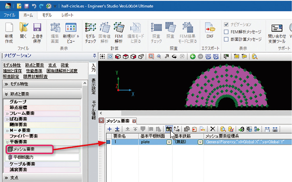
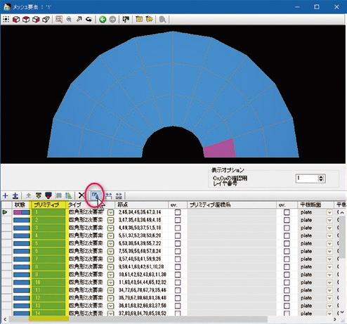
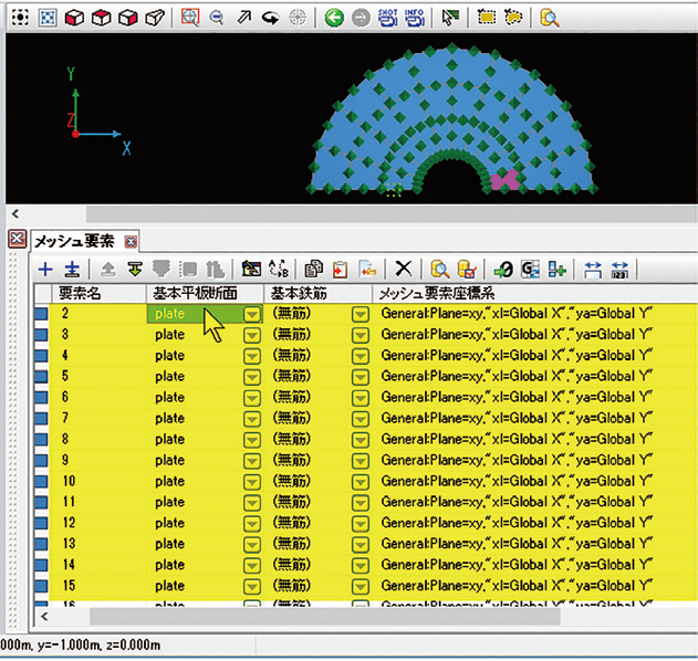
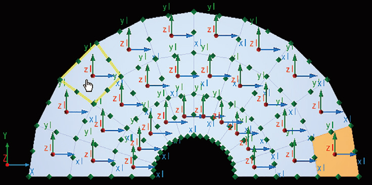
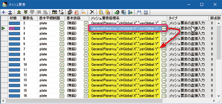
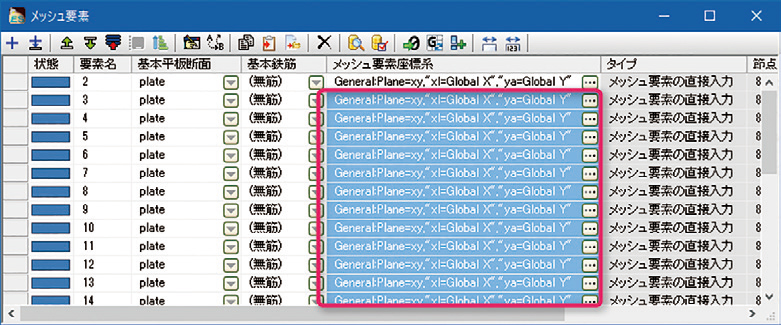
<Supplement>
It is important to check the mesh element coordinate system when multiple mesh elements are generated by decomposing one mesh element. If it is in an unintended orientation, you can copy the content of that cell and paste it to another cell (Yellow part in Figure 7) after setting the element coordinate system of one mesh element (the red frame part in Fig. 7). As shown in Fig. 8, if multiple cells are selected and pasted, it will be reflected at once.

Click to enlarge the image. Click to enlarge the image.
Figure 7 Copy mesh element coordinate system Figure 8 Paste multiple mesh element
coordinate systems simultaneously


Previous
  
Index
(Up&Coming '17 Fall issue)
Back
Up&Coming

FORUM8