| 4D simulation and movement setting |  |
| Support Topics | |||
| Support Topics / UC-win/Road | |||
|
|||
|
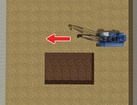
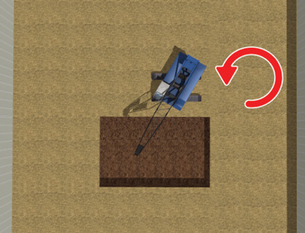
This time we introduce the 4D simulation function added in the UC-win/Road Ver.14.1. The 4D setting can add movements using time axis to 3D models. This allows users to create simulations of workflow linked with 3D model behaviors such as construction and product line in factory. Here we explain the function by using an example of crane in construction site. 1.Different use of motion expressions In this topic, we make a crane proceed forward and turn left. Since we do not want to make the crawler part of the crane to move when turning, we have to divide movements within one 3D model. The movement like this can be created by combining the 3D model movement settings in addition to the 4D simulation function. Here, 2 behaviors of proceeding and turning are simulated by the 3D model movement setting.
Fig.1 Two kinds of movements by using the model movement setting explained in this topic 2-1. Movement group setting Open the 3D model editor screen and go to the "Movement" tab. First, set a group and a hierarchy of 3D model parts based on the movement. This time, divide the layer into a turning part and non-turning part. The hierarchy is a tree structure. Movements set to upper groups are applied to lower group in the deeper position, but movement settings set to lower groups do not affect upper groups. 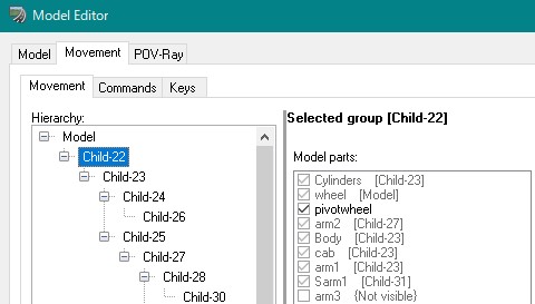 Fig.2 Movement group setting and hierarchy structure 2-2. Action setting Next, set actions to each movement group. You can select a translate action or a rotate action. If you select the translate action, decide a direction axis to go from XYZ, and specify a rotate axis or a position of rotate origin if you choose the rotate action. In this example, we make the crane move forward and do not move the crawler when turning. So the crawler part should be the highest group in the hierarchy. Select "Model" in the "Hierarchy" and check in the wheel part in the "Model parts" on the right. Click the "Add" button at the left bottom to set the proceeding action to the wheel. Name the action "Proceed" and set the "Translate" action and the "X" axis. This proceeding setting is applied to parts in the lower hierarchy as well as the wheel. Then, specify parts other than the crawler as the lower hierarchy group. Select the Model in the hierarchy structure and click "Add child". You can see that a layer named Child-1 is added under the Model. (A serial number will be given.) Put a check in the parts other than the crawler and click the "Add" at the bottom left. Name it "Turn", select "Rotate" for Action, "Y" for Axis, and "Centre" for About. This setting allows the parts other than the crawler to rotate. 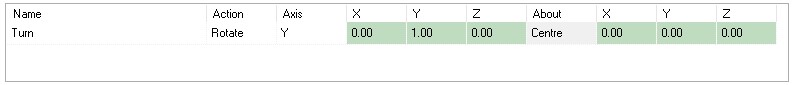 Fig.3 Action setting 2-3. Command / Key To configure movements, open the "Commands" tab, set movement commands to actions set in the group, and decide the amount and speed of translation/rotation and movement order. In the 4D simulation, the settings of the amount and speed of translation/rotation are defined in the task setting. If movement settings are already set to models, users can also select those configured actions. 3.4D simulation setting3-1. Task setting After configuring 3D models, use the Gantt chart and set a 4D simulation. In the Gantt chart, users can manage schedules such as 3D model behaviors and display timing by using the task setting. 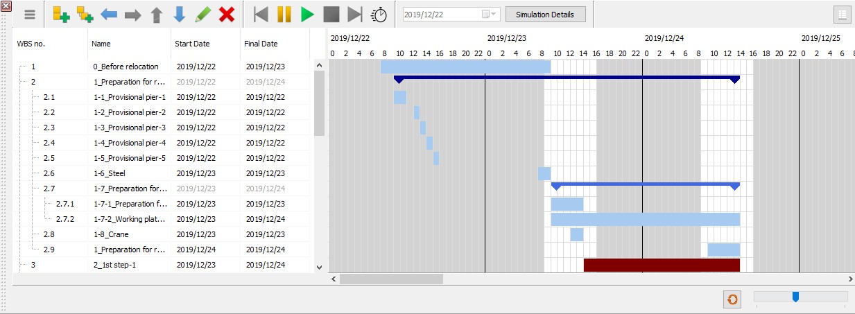
Fig.4 Example of the Gantt chart display At first, click "Add Task" in the Gantt chart. Right click on the added task and select "Edit Task" to define task start/end time information. More detailed schedules can be configured by adding subtasks and making a layered structure. 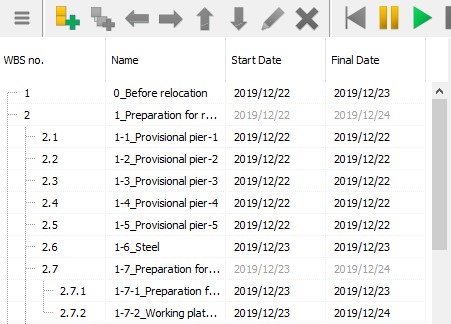
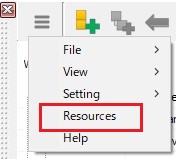
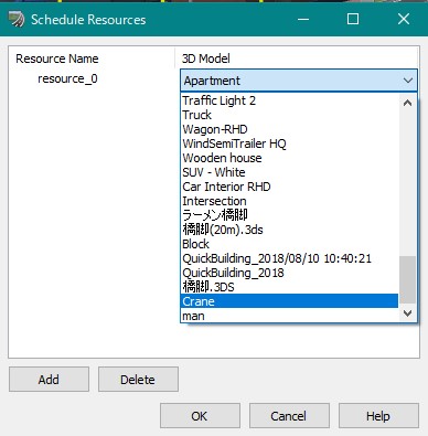
Fig.5 Task setting by adding layers 3-2. Register resources Register models to resource before selecting 3D models that move in 4D simulation. Click a button at the top left on the Gantt chart, go to "Resources", and click "Add" in the "Schedule Resources" window. It is a good idea to rename the name of the resources so that they can later be identified easier
Fig.6 Register resources 3-3. Resource allocation and command settings Next, configure model movements by using tasks. Right click on a task to use a registered model and click "Edit moving objects". 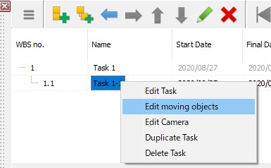
Fig.7 Task setting In order to set up the motion shown at the beginning of this topic for the crane, it is necessary to define two types of motion: Proceed and Turn. First, click the "Add" button three times on the "Moving Objects" screen that is opened by the operation explained above to add three command lines. In the first command, set a command to make a crane appear. In the "Resource Name", select the resource that the crane is registered and select "In Place Movement" for Movement Type. Then, specify the coordinate where the crane appears in the "Start Position" and the direction angle of the crane in the "Final Position / Rotation". Next, in the second command, configure the proceeding movement. Set the same resource as the first command, select "Predefined Movement" for Movement Type, and set "Proceeding" for Path. The distance of proceeding can be decided in the "Final Position / Rotation". Then, set the turning action in the third command. Select the same settings as the second command for the resource and the movement type. Choose "Turn" for Path and specify the rotation angle in the "Final Position / Rotation". At last, set Start Time and End Date for each of the three commands. For example, if Start Time is 9:00:00 and End Date is 10:00:00 in the first command, the model appears at 9 am on the Gantt chart and remains still for 1 hour. Then if the task schedule is set from 10:00:00 to 10:01:00 in the second command and from 11:00:00 to 11:01:00 in the third command, the model proceeds for 1 minute after standing still for 1 hour, stops until 11 am, turns for 1 minutes from 11 am, and remains still until the task finishes. 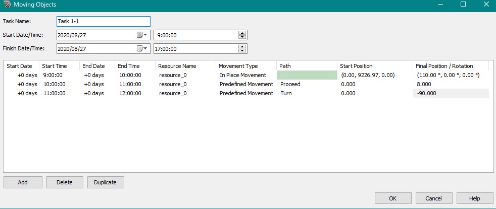
Fig.8 Example of command Now that the 4D simulation settings are complete. The configured movements can be checked by clicking the play button. When the button is pressed, a red bar showing the passage of time is displayed in the Gantt chart, and tasks and commands set in the Gantt chart are executed according to the movement of it. The visual movement speed depends on the simulation speed setting (the speed of time flow). The time to be displayed can be changed by clicking in the Gantt chart. 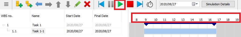
Fig.9 Execution of 4D simulation 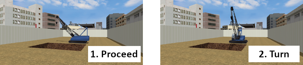
Fig.10 4D simulation in progress Conclusion In addition to the setting explained in this topic, users can use a variety of settings such as the route movement of 3D model, camera position setting, highlighting display, etc. With the 4D simulation function, users can easily simulate constructions and loadings that need a strict time transition simulation. The CityDesign sample data preinstalled in the UC-win/Road includes the 4D simulation setting expressing the railroad track replacement construction at Shibuya station. This sample data will help users to fully utilize the 4D simulation function. 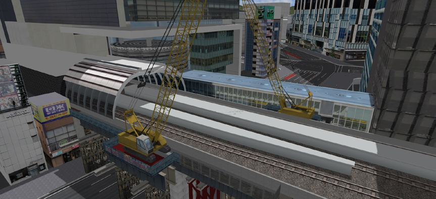
Fig.11 Simulation of the railway track replacement construction |
|
|||
| (Up&Coming '20 Summer issue) | |||
 |