International Newsletter vol.43 2011/2
2.28.2011 FORUM8 Co., Ltd. http://www.forum8.com/
|
| New Product Information - Engineer's Studio(TM) Ver.1.06.00 |
|
Price: US$3,300(Base)/Free revision
up
Release date: December
2010 |
Dynamic
Nonlinear Analysis |
|
In Engineer's
StudioTM Ver 1.06.00, the following three functions have been
added/improved. All of them are the features for free revision up.
- Solver
- Plate Element Input & Output
- User interface performance for large models
|
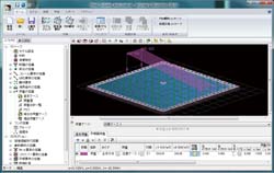
The PARDISO(Parallel Direct Solver) Sparse Matrix Solver (supported by the
Intel MKL library) has been implemented in the solver. PARADISO was originally
developed by the University of Basel, Switzerland. It greatly increases the
performance of the solver on large models. Memory usage is significantly reduced
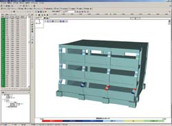
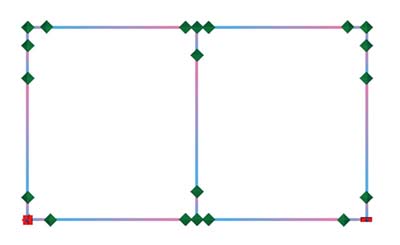
and calculation times are significantly improved .For example, a 45000 node
model (plate elements, material nonlinear, static analysis, 50 steps) (Figure1)
uses 3GB of memory compared with 20GB in the previous version. This model
calculates in 30 minutes compared with 20 hours in the previous version. Eigen
analysis uses less than 1GB of memory whereas the previous version required
memory amounts beyond the limits of typically available desktop PCs and could
not run. This model calculates in one minute compared with an estimated two
hours in the previous version if memory had been available. This new feature in
conjunction with the previously released 64 bit solver option has significantly
increased the model size capabilities (number of nodes) of Engineers Studio.
Plate element models typically generate larger node counts than frame element
models. The PARADISO solver performs excellently over the full range of model
sizes typically found in Engineers Studio.
The initial stiffness of the
asymmetric bilinear spring has been changed from zero to the primary stiffness.
This spring type is typically used to model bilinear soil to concrete structure
interactions and with this improvement the model will now be stable in its
initial state. This means that the boundary conditions for the whole model can
be described by only the soil/structure interaction and previous remedies such
as dummy springs of small stiffness are no longer necessary.
The previous
restriction of 1000 child nodes per rigid body element has been removed. There
is no restriction now.
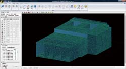 |
 Figure1:45000 node model Figure1:45000 node model |
|
| Plate
Element Input & Output |
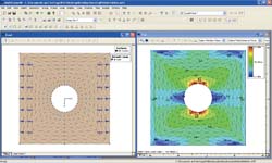
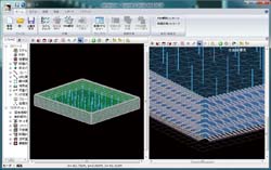
A new generator command was added to quickly create distributed nonlinear springs over surface areas of plate elements. Soil property profiles including layer thickness and stiffness (kN/m3) are input and all required spring definitions, spring elements, nodes and support conditions are automatically generated at each node of the plate elements selected.(Figure2a, b). This involves the integration of the stiffness over the element shape to produce equivalent node stiffness values. These integrals are calculated and the required spring definitions automatically generated.
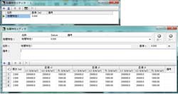
A new feature was added
to the plate element loading feature. Offsets from the sides of the loaded
region are now possible. This gives control in 2D over the surface and enables
partial loading completely within a single element. (Figure3)
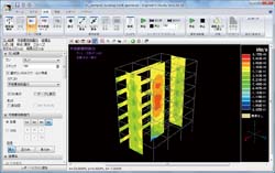
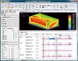
Maxima for
contour plots of the results of plate elements are now prepared per user defined
group (Figure4). Previous versions stored and reported the maxima for contour
plots over the whole model. Fibre strain results for fibre elements are now
prepared per group to give consistent treatment of strain results between plate
elements and fibre elements. A new delete function was added to the edit window
of the plate element "mesh element editor". Now when multiple primitives are
selected by the mouse they can be deleted by the delete button or from the right
click menu delete option. The option to delete unused nodes after deleting
primitives is also included in the new command.
Improvements to the plate
element creation from outlines were done. Now nodes in existing elements can be
optionally included in the mesh creation of the new element. This permits much
easier building of a correctly connected model. The result of load case
combinations are now shown for the contour figures of plate element
models.
 |
|
 |
| Figure2a:Ground spring automatic generator |
|
Figure2b:Input of soil stiffness property |
 |
|
 |
| Figure3:Bilateral offset function of plate loads |
|
Figure4:Contour Figure per group |
|
| User
interface performance for large models |
Large plate element models typically require much higher node
counts than beam models. Many improvements have been made to improve the
response of the user interface on large models. Models of around 45000 nodes are
now manipulated with ease.
In models with many load steps and many cells
in a fibre section, the display of the fibre section results was very slow.
Improvements have been made. This data caused performance problems when reading
and writing files.
The process speed of the following items is improved.
- Input window access from [Input navigation]
- Result display of frame element
- Improved speed of 3D model drawing
- Range selection of a large number of nodes and element
- Result display of fibre element
- Reduced size of input data file
- Improved speed of file loading
|
|
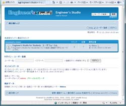 |
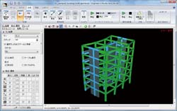
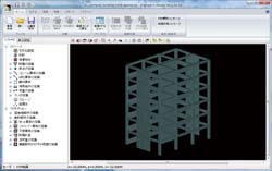
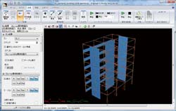
Figure5:Image of Engineer's StudioTM
User forum to be
opened |
|
|
|
|
| New Product Information - UC-win/FRAME(3D) Ver.5 |
|
Price: US$6,800(New purchase)/US$1,000(Version up)
Release date: January 2011 |
|
UC-win/FRAME(3D) is a
general-purpose 3D frame analysis program. The Advanced version, a
top-of-the-line software allows static and dynamic analysis considering both the
material nonlinearity and geometry nonlinearity. It has some verification
functions including allowable stress, bending strength, shear strength, and
nonlinear member.
For this time, the following three functions are
added.
|
| Reduced stiffness in the eigenvalue analysis(Automatic calculation of yield
rigidity) |
The following sentences are stated in the expository writing of
"6.2.3 Calculation method of eigen cycle", "March 2002 Highway Bridge
Specification V Seismic Design Volume, dynamic verification with wide
application range, Japan road Association".
| As for the stiffness of bridge pier ------(snip)------, the yield rigidity
of bridge pier is used for the verification of seismic capacity for the
level2 earthquake. |
It is designed
to fulfill the seismic capacity of the whole bridge by absorbing the energy due
to the plastic member when the strong earthquake such as level 2 occurs. When
the plastic performance is applied for the member, the stiffness is reduced and
the eigen cycle is becoming long. Though it is necessary to calculate repeatedly
to analysis exactly based on the expository writing of the Highway Bridge
Specification.
In the previous version of FRAME(3D), the yield rigidity was automatically
calculated from the section shape and acting axial force by setting "bilinear"
or "linear" as the M-φ property category, and the eigen cycle was calculated. When "Tri-linear"
or "Tetra-linear" is selected in the category and the eigenvalue
analysis is performed, the obtained eigen cycle is the value which is calculated
with the cracked stiffness.Therefore, when the time history response analysis
is performed with "Tri-linear" or "Tetra-linear", it
was necessary to prepare the separate model for the eigen cycle calculation.
For
this time, the switch is added to use the yield rigidity for eigenvalue analysis
in these cases.It is unnecessary to calculate the yield rigidity
separately.
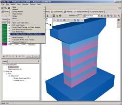
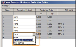
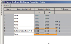
- Select "Edit the stiffness reduction value in eigenvalue analysis"
from model menu(Figure1).
- Select the element to be reduced and choose the method for it.
It is possible to select from the method where the ratio of cracked stiffness
and yield rigidity from M-φ property is automatically calculated to use
it the reduction ratio or the user defined method(Figure2).
|
 |
|
 |
 |
 |
| Figure1:Selection of model menu |
|
Figure2:Selection of the element to be reduced and method |
|
| Support for
Railway live loading |
UC-win/FRAME(3D) has the function of influencing line analysis and the
loading type was mainly based on the Highway Bridge Specification.
For this
time, it is improved to input EA loading based on "April 2004 Railway Structure
Design Specification, Concrete Structure".
The EA loading is the combination
of axle load group (multiple concentrated load) of the tracked train and the
load of tracked goods train.
 |
| Figure3:EA loading input image |
|
| DWG/DXF output of model and section force |
DWG/DXF format is supported for the model and section force diagram after
calculation. Therefore, they can be edited with CAD software(Figure4).
 |
|
 |
| Figure4:Moment(Left: UC-win/FRAME(3D). Right:DWG file) |
In the analysis model, the fulcrum conditions are displayed as well as
the element(Figure5).
 |
 |
| Figure5:Model diagram(Top: UC-win/FRAME(3D), Bottom: DWG file) |
|
|
|
| Architectural and Structural Analysis Support Service |
|
Architectural and Structural
Analysis Support Service |
|
Multiframe,UC-win/FRAME(3D),Engineer's Studio(TM)Analysis Support
Service |
|
Start of the service: October 2010 |
|
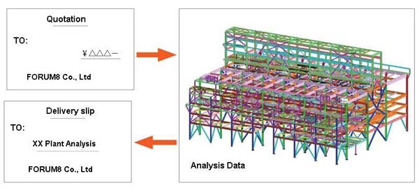
FORUM8 is providing both architectural analysis support service as well as
the existing structural analysis. Multiframe, UC-win/FRAME(3D), and Engineer'sStudio(TM)are used
for this service.
|
We will first request for the structural drawing and the load case for
the cost estimation. Next, the estimation sheet is submitted to the customer.
After confirmation of the analysis contents and the estimation cost, our
technical staff will start working.
Our technical staff creates the analysis data
together with the customers to provide the appropriate analysis result where the
input data, optionally section force data are sorted out. We will provide
support for any inquiries after submission of the analysis data.
|
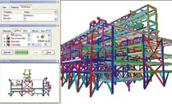
Multiframe is the structural engineering analysis software developed by
Formation Design Systems in Australia. Its first version was released for
Macintosh and this software has been used by more than 3,000 users in all over
the world. It allows the section calculation based on the standard in each
country. In Ver.12, it supports for the plane elements to perform a wider range
of analysis.
|
| What is
UC-win/FRAME(3D)? |
UC-win/FRAME(3D) is the 3D analysis program for space-framed structures. The
Advanced version allows the static and dynamic analysis based on the material
nonlinearity and geometric nonlinearity.
It has various verification features
for the allowable stress, flexural capacity, shear capacity, and nonlinear
members. Our analysis support team won the contest sponsored by the National
Research Institute for Earth Science and Disaster Prevention in Japan : "C1-2
E-Defense Pre-analysis contest of Full scale RC Pier Earthquake Resistance
Experiment, fiber model" with
UC-win/FRAME(3D).
|
| What is
Engineer's Studio(TM)? |
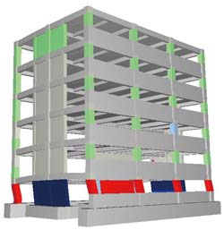
Engineer's Studio(TM) is the 3D plate dynamic nonlinear analysis program.
The function for nonlinear plate elements is added to UC-win/FRAME(3D). The
constitutive law of WCOMD which was developed by the concrete laboratory in
Tokyo University is applied for the nonlinear RC plane elements.
Our analysis
support team won the contest sponsored by the National Research Institute for
Earth Science and Disaster Prevention in Japan : "C1-6 E-Defense Pre-analysis
Contest of Full scale RC Pier Earthquake Resistance Experiment using nature
mortar" with Engineer's Studio(TM).
|
|
| Conferences, training and seminars |
| Upcoming Events |
|
Seminars in Shanghai,
Beijing and Seoul will be held on the following
schedule.
Venue:
Shanghai - Shanghai
Seminar room (FORUM8 Technology Development(Shanghai) Co.,
Ltd)
Seoul-FORUM 8 Korean
Office
| Seminar |
Date |
City |
| UC-win/Road
VR |
March 9th, 2011 |
Seoul |
| May 6th, 2011 |
Shanghai |
| UC-win/Road
SDK |
May 17th, 2011 |
Shanghai |
Engineer's
Studio(TM),
Engineer's Studio(TM)(2D)) |
March 24th, 2011 |
Shanghai |
| April 13th, 2011 |
Seoul |
| VR-Studio(TM) |
April 7th, 2011 |
Shanghai |
| EXODUS / SMARTFIRE |
March 3rd, 2011 |
Shanghai |
| May 10th, 2011 |
Seoul |
| xpswmm |
March 16th , 2011 |
Seoul |
| OSCADY/TRANSYT |
March 10th, 2011 |
Shanghai |
| March 23rd, 2011 |
Seoul |
| Design Builder |
March 30th, 2011 |
Seoul |
| Retaining wall design Ver.2 /Temporary sheating
work design Ver.2 |
March 17th , 2011 |
Shanghai |
| April 20th, 2011 |
Seoul |
| Participation Fee |
| Participation Fee |
Free |
For more information and applications, please email us
at
mailto:forum8@forum8.co.jp
Gross circulation: 5518
To
subscribe this page, go to http://www.forum8.co.jp/english/p-mail-e.htm
If
you would like to unsubscribe from our newsletters, please include
"Unsubscribe"
in the subject title of your email and send it back to
us.
Thank you for your continued support.
FORUM8 Co., Ltd.
mailto:forum8@forum8.co.jp
2-1-1 Nakameguro GT Tower 15F
Kamimeguro
Meguro-ku Tokyo 153-0051 JAPAN
TEL +81-3-5773-1888
FAX
+81-3-5720-5688
http://www.forum8.com/
|