International Newsletter vol.21 2009/7
7.2.2009 FORUM8 Co., Ltd
----Contents----
--------What's New at FORUM8--------
- French Premier Partner's Success with UC-win/Road
- Collaboration News (GRAITEC)
- Beijing tepia Technology Co., Ltd
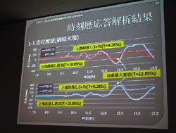
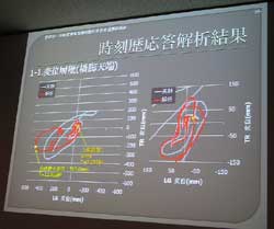
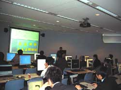
- C1-2 Experiment Pre-analysis contest (Seminar Report)
- Experience Seminar "Allplan" BIM Solution (Seminar Report)
- Experience Seminar for the Engineer's Studio (Seminar Report)
- New Product and Upgrade Information
- New Series "100 Best Bridges"
- Support Topics
--------Upcoming Events--------
- Upcoming International Events
- Seminar in Shanghai, Beijing, and Seoul
--------FORUM8 Homepage Information--------
- Web Estimate Service
- Technical Support Service for UC-win/Road Overseas Users
- User Information Page
|
|||
David Remaud of itech ( www.itech-soft.com ) a Forum 8 Premier Partner based in Paris commented "We first came across Forum 8 when researching the market for 3D simulation software for engineering applications. We are a company that specializes in the design, development and distribution of structural computation software packages for use in the construction, civil engineering, roads and mechanical engineering sectors. "Forum 8 seemed like a very dynamic and responsive company and we immediately began working together. In fact our first project was the design of a user interface for one of their Geo visualization packages. "The next stage in our involvement with this market leading Japanese 3D VR software specialist was to become an active distributor of their software. "The initial result was the sale of a system to a University closely followed by an approach from a huge manufacturing company here in France that wanted to utilize the Forum 8 3D Virtual Reality (VR) simulation software within their Driver Training Simulator. "We will be revealing full details of this exciting new client very soon. However, what I can reveal is that they chose the Japanese software for a number of reasons, including its preeminence as the leading simulation software in the highly competitive Japanese and Korean markets and their experience with the Japanese Type N700 Shinkansen (Bullet Train) Simulator for training drivers and conductors. "Apart from the comprehensive features of the software, they were also looking for a supplier that could guarantee a high level of technical support from both the software manufacturer as well as from its local Partner. I'm pleased to say that they found the combination of itech, Forum 8 and UC-win/Road to be the perfect solution." Editor's Note: UC-win/Road is state-of-the-art interactive 3D Virtual Reality (VR) simulation software. Users can manipulate dynamic 3D space, import and edit CAD data, build and texture block models, view multiple design alternatives in real-time, as well as being able to visualize and edit intelligent traffic & much more... See www.forum8.com More information contact: Brendan Hafferty brendan@forum8.com Forum 8 European Office, Holborn Gate, 330 High Holborn, London WC1V T: +44 (0)20 7203 8300 M: +353 86 858 4873 W: www.forum8.com |
|||
|
|||||
Graitec found in 1986 offers an integrated solution of BIM design through Advance suite; Advance Steel (for steel construction), Advance Concrete (for reinforced concrete construction) and Advance Design (for the structural analysis). Graitec, the third world biggest software provider in the civil engineering and construction fields, has twelve companies and more than thirty sales agencies in Europe and also including North America. Advance Steel, developed for industry professionals automates the entire stuructural CAD process (fabrication, erection drawings, various reports). Now they have as many as 30,000 users all over the world for the Advance Steel as one of their leading products. FORUM8 has an exclusive sales rights, localizing it for Japanese market. Last September, we invited an international sales manager and an engineer of Graitec to the 2nd FORUM8 Design Conference and they presented the special lecture under the theme of "3D Steel Structural CAD for BIM". When they come to Japan for a business trip etc, we get them to take the time to give a technical lecture to our staff. Also, FORUM8 and Graitec are actively taking technical or information exchange.
(Up & Coming 2009 fresh geen leaves issue) |
http://www.hydro-soft.cn http://www.hydro-soft.co.jp |
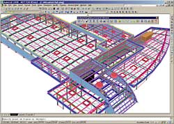
Tepia, which have proven track records in water related business activities, is offering sales and technical supports of UC-win/Road for xpswmm, which link with the xpswmm, Rainfall-runoff / Inundation analysis software of FORUM8 products series. This tool allows you to visualize and check the condition of overflowing in streams To expand distribution of products through link with FORUM8, Tepia increased sales staffs and VR data creating staffs. They will plan to send their excellent staff to FORUM8. Those activities produce a good result such as learning the latest skill of UC-win/Road, improvement of sales skills and technical supports and acquiring 3D CG / VR trends. Also, they Tepia and FORUM8 will exhibit on conferences together for increasing our market share. We'll do our best to measure up to your expectations for distribution in China, including Beijing. |
|
| Report of the C1-2 Experiment Pre-analysis Contest | |||||||||||||||
|
|||||||||||||||
| Report of Experience Seminar "Allplan" BIM Solution | |||||||||||
|
| Experience Seminar for the Engineer's Studio | ||||
|

3Dimentional Real time Virtual Reality
Advanced 945,000yen / Standard 609,000yen
Support for multiple languages; Japnese, English, French, Korean and Chinese
vr.forum8.jp
Added to Product Lineup as a new VR system software in three and half years concept.
Support large scale space, multi-user, multi-core, multi-reality
More Advanced and Cutting-edged 3D Real time Virtual Reality
Drive Simulator
Main New Features of Ver.3.4.x
Support for sub scenarios and simultaneously execution of scenarios
Expanded Events Action
Support for display of tire rotation of vehicle wheel and rudder angle
Micro Simulation Player
Support for sub scenarios and simultaneously execution of scenarios
Expanded Events Action
Support for display of tire rotation of vehicle wheel and rudder angle
Micro Simulation Player
For more information, click to see OpenmicroSim.org

VR Presentation and New Urban Development
Special Contribution by Mr. Tadao Ando
UC-win/Road Ver.3.4 trial version included
Case Examples of VR Presentation
Written by Fukuda Tomohiro / Fumio Seki and others
Price: 3,990yen
Published by X-Knowledge
160 pages with full page color
Release date: November 19th, 2008
Please go to http://www.forum8.com/english/topics-e.htm for updated information on Up & Coming.
|
||||||||||||||||||||||||||||||||||||
|
||||||||||||||||||||||||||||||||||||
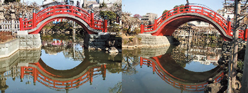
You can see the two large and small arched bridges in the precincts of Kameido shrine, Koto ward. They are each called Otoko-Bashi, Onna-Bashi, from the right. Otoko-bashi stands for a mountain of hardship in the past and Onna-Bashi stands for future. The shrine says that crossing these bridges, you can arrived in front of a god. Before they were vermilion-lacquered bridges, but they were damaged by a war and re-constructed as a concrete arch bridge in 1952. The shrine is called as Kameido Tenmangu, which stands for a shrine dedicated to Sugawara no Michizane, the patron saint of scholarship, and famous as a grand shrine in the Edo period as well as Fukagawa Hachimangu. They are erected in imitation of Dazaifu Tenmangu of Kyushu in the eras of Tsunayoshi's Bakufu, and the time of Sugawara no Michizane as an enshrined deity: it must be a tutelary deity for a newly developed land. Also the precincts of Kameido shrine are known for a noted place of 80 roots of wisteria, which are drawn in a print at that time; it is used in the cover page of the 100 bridges.
As locating the Edo-Bakufu, Tokugawa Ieyasu built the bridge to link with the new city, which are made by reclaiming the part of sea in 1603. You could say that Town creation of Tokyo started from construction of the Nihon-bashi. Next year, the five main highways such as Tokaido were defined starting from here. Current Nihon-Bashi is a stone-built arch erected in 1911. It is designated as an important cultural property, marked a milestone and a ornamental top of a railing. You could say that its design is the most important work of a combination of Japanese, Chinese and European styles. Its bridge name was called Nihon-Bashi after the Nihon-Bashi river. Because a highway was built directly above the bridge in 1964, there has been a lot of controversy about bridge landscape; it should be removed or moved. People are searching re-construction plans. There are some plan that it should imitate the Cheonggyecheon, Seoul, South Korea, which is a good case that Lee Myung-bak, Seoul mayor then re-established a stream and landscape by removing the elevated highway and restoring the stream.
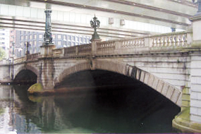
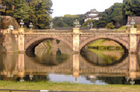
The photo shows a steel bridge crossing the imperial moat, and there are stone-built bridges at the back; a stone-built bridge is called "Nishinomaru Ote-Bashi" and a steel bridge is called "Nishinomaru Shimojo-Bashi" Nijuu-Bashi, which is crossed over deep moats and the girder supporting piers, is called after a double structural crossing technique. It was a wood structural arch bridge(Total Length: 29m, Width: 6.5m) in the Edo period, but was replaced with a steel bridge made in Germany in 1888, by asking a Germany company to do that. After that, they are reborn in 1964. Though the Imperial Household Agency calls the stone-built bridge for "Seimon Ishibashi", the steel bridge for "Seimon Tetsubashi", in general they are collectively called "Nijui-Bashi"
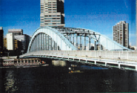
Eidai-Bashi was crossed by Tokugawa-Bakufu in 1698; it was fourth bridge crossed in Suminda River, following Ryogoku-Bashi, Shin-Ohashi, and Azuma-Bashi. The size of the wooden bridge at that time was 200m × 6m. In 1698 during the Fukagawa-Tomioka Hachiman Festival, terrible catastrophe happened, which was caused by weight limit over. The bridge fell down because quite a lot of viewers gathered in the one place. The people in charge were punished with banishment to a distant island. In 1897 it was replaced with a steel bridge, above 200m away from the original. The finished bride was huge construction with the size of 200m x 14m, which attracted people's attention; it cost as much as 83,650 yen and took three and half years for construction. After that it was replaced in 1926. Compared with Kiyoshu-Bashi, it looks more masculine and has heavier weight. It has been read as "Eidaiha doshinto oita youni kake" meaning "Eidai-Bashi was crossed as if it was with a solid appearance" in Senryu.
|
||||||||||||||||||||||||||||||||||||


|
|||||
|
|||||
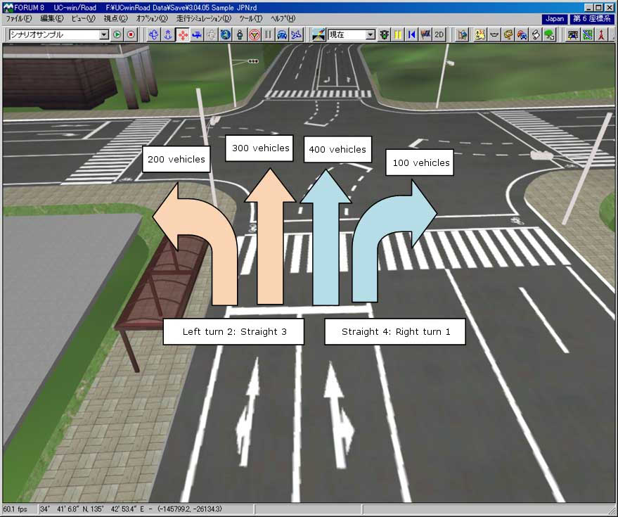
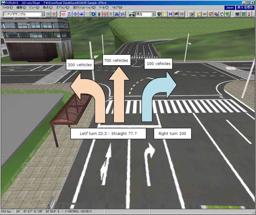
| When you set the traffic volume in UC-win/Road, you need to input it by
road unit. You enter the number of vehicle from the start point of each road to
the end point. For example, in case that two traffic lanes which traffic volume
is 10000 vehicles. 500 vehicles are divided on each traffic lane. When you
assign the weight to each right turn / straight / left turn at the intersection,
you need to set the number of driving vehicles on each lane. If you want to set as: Left turn: 200 vehicles as 20% Straight: 700 vehicles as 70% Right turn: 100 vehicles as 10% Given in two-lane road, you need to set as: Left lane/ Left turn:3, Straight:3 Right lane/ Straight: 4, Right turn:1 When the right-lane will become the right-turn lane, you need to shift vehicles to the left-lane until the intersection. To make the right-turn to be the 10 percent of the total share, you need to shift the 80 percent of vehicles, 400 vehicles, from the right lane to the left lane. As a result, the traffic volume will be as below. Left lane: 90% as 900 vehicles Right lane: 10% as 100 vehicles Left lane/ Left-turn:22.2, Straight 77.7 Right lane/ Right-turn: 100 Above vehicle-shift setting can be set at the behavior control points. Vehicle setting is also important as well as weighting of vehicles at the intersection. For example, the number of vehicle at the next intersection depends on the weighting of assigned vehicles. If the setting of the vehicle which go straight doesn't be established, they all will drive in the left lane. There is not so much influence on the other intersection when the setting is established in the only one intersection, but if you consider a network configured by multiple intersection, you need to consider the influence.
|
|||||
|
|||||
|
|||||
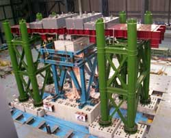
We introduce how to export from "Seismic coefficient calculation (Bearing Design)", and how to model the pier with an angle of skew. First, when you export data from the Seismic coefficient calculation (Bearing Design) to the UC-win/FRAME(3D), the model are automatically created as following.
Seen from above, the model are crossed toward the super-structure and its bevelθ is 90 degrees. To rotate pier members, two methods are available. Method1 1) Select member(s) 2) Enter the arranged angle of section in the general tab of member edit window Method2 1) Select member(s) 2) Right click to show the pop-up menu and select [the association between the element Y axis and the global coordinate system] 3) Enter a vector Method1 is the way to set the arranged angle of the section for the element coordinate system, so if you enter an angle, only the main axis coordinate system rotate but the element coordinate system doesn't rotate. Method2 is to set the angle of the element coordinate system. The main axis coordinate system rotates then; Both the element coordinate system and the main axis coordinate system rotate at the same time. Please look at the following.
The image above left shows the method1 and right image shows the method2, which is rotated. Though each coordinate system is rotated 30 degrees, the left image shows only the main axis coordinate system(subscript is p) rotating, and the element coordinate system (subscript is l) isn't rotated. Regarding the right image, both the main axis coordinate system and the element coordinate system rotate. This doesn't influence on the analysis result, but you should take method2, for it is easier than method1. For more information, please refer to the following help. [Operation method | Model creations | Model(5) - the coordinate system-] [Operation method | Model creations | Model(6) - Model (6) - The specification of the direction of the element coordinate system -] Please make sure to rotate the coordinate system of fulcrum, when you changed the angle of pier. If you forget to change it, as the right image showing, the footing and the fulcrum can't match.
Functions introduced above are effective for you to create skew bridge models or curved bridge models. Please make use it. |
The seminars provide attendees an opportunity to acquire up-to-date information about our product.
One of the main goals of these seminars is to explain analysis and design
techniques which abound in the industry. Participation fee is free!
| International Seminar Venue Shanghai - Shanghai Seminar room (FORUM8 Technology Development (Shanghai) Co., Ltd.) Beijing - Conference room (Beijing Tepia Technology Co.,Ltd) Seoul - Seminar room (BasisSoft, Inc.) |
||
| Seminar | Date | Venue |
| UC-win/Road - VR | 9 July 2009 | Shenzhen |
| UC-win/Road Advanced | 24 September 2009 | Shenzhen |
| UC-win/Road for Civil 3D | 18 August 2009 | Shenzhen |
| UC-win/Road SDK | 15 September 2009 | Shanghai / Beijing / Shenzhen |
| 16 September 2009 | Seoul | |
| Engineer's Studio/ UC-win/FRAME (3D) | 15 August 2009 | Shanghai / Beijing / Shenzhen |
| 8 September 2009 | Seoul | |
| GeoFEAS2D / GeoFEAS 3D | 4 August 2009 | Shanghai / Beijing / Shenzhen |
| 10 September 2009 | Seoul | |
| EXODUS - SMARTFIRE | 15 July 2009 | Seoul |
| OSCADY/TRANSYT | 6 August 2009 | Seoul |
| DesignBuilder | 25 June 2009 | Shanghai and Beijing |
| 26 June 2009 | Seoul | |
| Summary | ||
| Participation Fee | Free | |
| Application | ||
| For more information and application submission, please
email us at forum8@forum8.co.jp |
||
We will participate in a number of overseas events. Please come to visit us in the booth to learn
more about our product line-up. Look forward to meeting you!
ITS AP Bangkok
8-10 July 2009
http://its-ap2009.in.th/
2009 AITPM National Conference
5 -7 August 2009
http://www.aitpm.com/conf-upcoming.html
ITS Stockholm 2009
21-25 September 2009
http://www.itsworldcongress.com
Free web quotation service is available at the following site. Explore sample projects,
experiment and create!
https://www2.forum8.co.jp/road_est_en/html/main.htm
- Technical support service for UC-win/Road overseas users
The support service undertakes data generation tasks related to UC-win/Road such
as the generation of 3D VR simulation data, 3D models and textures,providing support for
road businesses, urban development planning, public projects, private
developments and so forth through extensive simulation tasks creating cost-affordable, high-quality data.
For more information, please go to the following site.
http://www.forum8.co.jp/english/uc-win/road-support-e.htm
- User information page
Marketing materials and updates can be retrieved and downloaded from the following site.
https://www2.forum8.co.jp/scripts/f8uinfEN.dll/login
Gross circulation: 3,522
If submitting a formal request to unsubscribe from our mailing list, please include "Unsubscribe"
in the subject title of your email and send it back to us.
Thank you for your continued support.
FORUM8 Co., Ltd. mailto:forum8@forum8.co.jp
2-1-1 Nakamegruro GT Tower 15F
Kamimeguro Meguro-ku Tokyo 153-0051 JAPAN
TEL +81-3-5773-1888
FAX +81-3-5720-5688
http://www.forum8.com