| Support Topics / Engineer's Studio® |  |
|
| Differences among setting methods of residual displacement |
| Support Topics | ||||
|
||||
| Overview |
residual displacement verification is conducted according to the specifications for highway bridges, part V Seismic Design (2002-2012)
and documents below:
The following are the features:
|
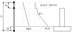
| Differences between the pier foundation and the foundation bottom |
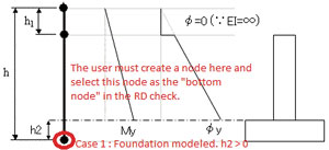
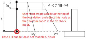
| h in the figure 3 varies by presence or absence of the footing. With footing Enter the height from the foundation bottom in h and the footing thickness in h2 (Fig. 4). Without footing Enter the height from the pier foundation in h and 0 in h2 (Fig. 5).
|
| Example |
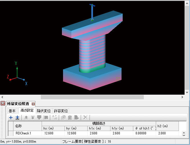
An input example for the pier like the figure 6 is below. It is 2.6 meters
high from the top of the beam to the position in the upper structure where
inertia force acts. This is the dynamic analysis which doesn't take the
basic spring into account, consider the footing bottom to be fixed, and
applies the type ll seismic movement 3 wave form to the direction of the
bridge axis. It has the M-φ element in the post foundation and the elastic
beam element in the middle part of the post.
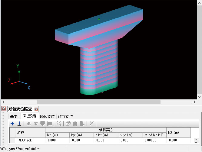
Case 1 This is an example of the modeling of the footing and that of the position of the gravity center in the upper structure (Fig. 7). Mass 598t, which corresponds to the shared weight of the upper structure, is in 2.6m high above the top of the beam. The surround of the bridge axis of the spring element that means the bearing is free at right angles in order not to let the moment affect the top of the beam. In this case, the height would be entered as "h=12.6m, h1=2.6m, h2=2m". Yield displacement would be 41mm in 2.6m above the top of the beam. Case 2 This is the modeling without the footing and the upper structure position like the figure 8. Mass 598t, which corresponds to the shared weight of the upper structure, is located at the top of the beam. The height would be entered as "h=8m, h1=0m, h2=0m", and the yield displacement would be 23mm at the top of the beam.
|
| Result Comparizon |
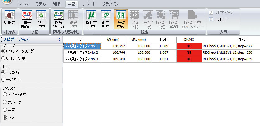
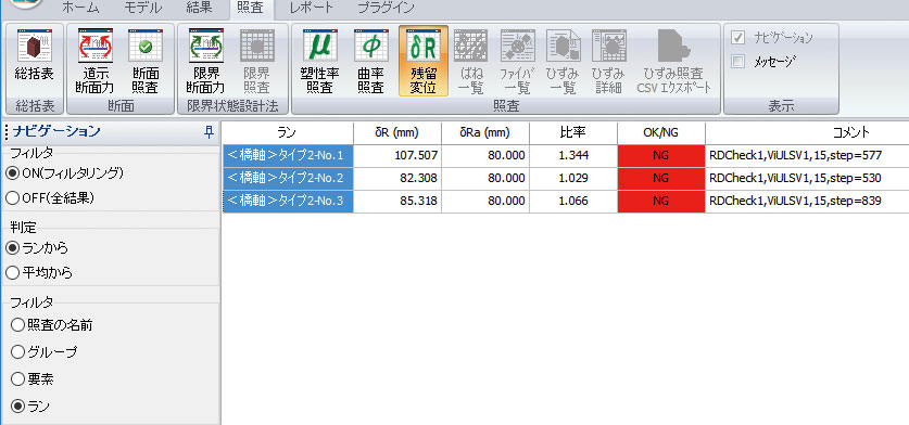
The results are shown in the figure 9 and 10. Both of the residual displacement
δR and the allowable value δRa are larger by 30% in the case
1. Thus the ratio of the allowable value is almost the same (difference
of about 3%).
|
| Conclusion |
| Case 1 is the model like taking out one from the entire system. In the
case 2, the seismic horizontal strength method of the single post RC pier
is modelized in regard to the direction of the bridge axis. By the modeling
method, we can see that the difference in the residual displacement amount
and the allowable value, but the design safe rate is almost the same. The
residual displacement was 4.7mm in the static verification. If exported from our product "Pier Design", the data of the skeleton model would be as that of the case 1 and the residual displacement as that of the case 2. The result of the residual displacement verification would be largely similar to that of the case 2. Since the exact modelization method is unclear as it is now, it would be grateful if these case studies about the modeling and the input of the residual displacement verification help your practical design. |
|
|||
| (Up&Coming 2016 Summer issue) | |||
 |
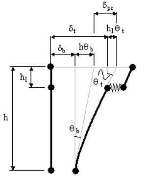
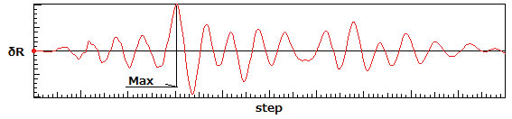
 Fig. 1 Conceptual diagram of δpr