|
FEM analysis result has a function to display bending moment distribution
map and its value table. At this time, you have two ways to select which
load case to be displayed (Fig. 1).
(1) Load case that is inverted in blue by clicking
(Select one from multiple load cases)
(2) Load case with its tick box ticked
(Display results of multiple load cases)
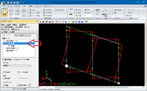
| A case of (1): |
|
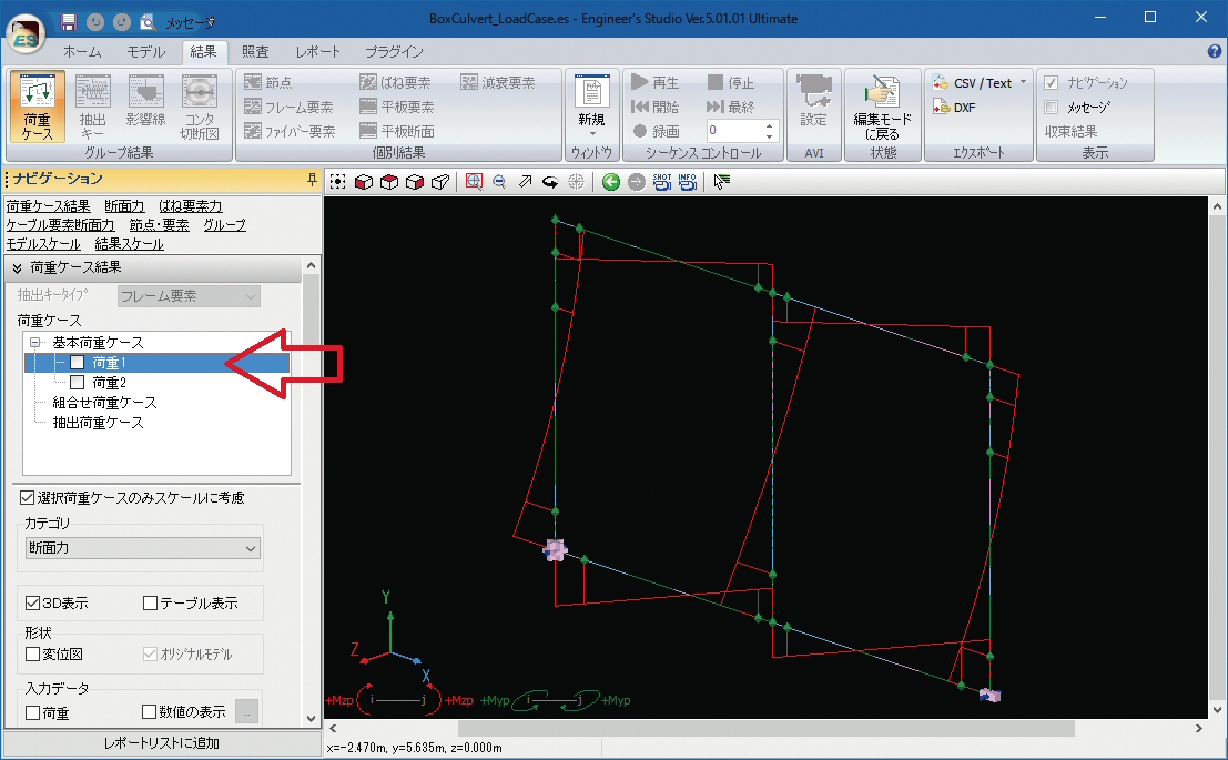
Bending moment of only the "load case 1" is displayed in the
figure 2.
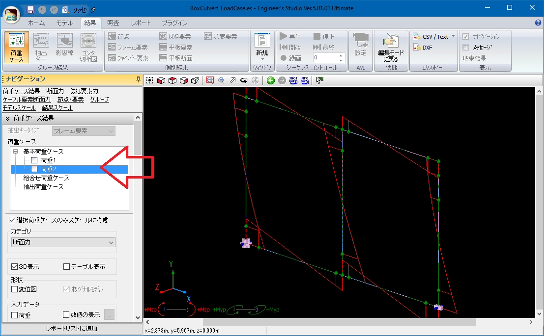
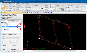
Bending moment of only the "load case 2" is displayed in the
figure 3. |
|
|
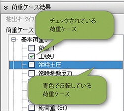 |
 Fig. 1 Two types of selected condition: Fig. 1 Two types of selected condition:
ticked and inverted in blue |
 |
 |
| Fig. 2 Bending moment of only the "load case 1" |
Fig. 3 Bending moment of only the "load case 2" |
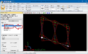
| A case of (2): |
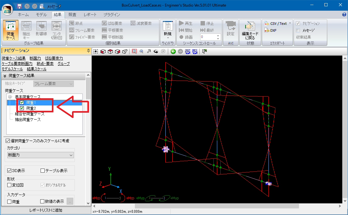
The figure 4 is a example that bending moment of both of "load case
1" and "load case 2" are displayed. Perform the operation
(2) when you want to display more than one bending moments. |
A case of
(1) + (2): |
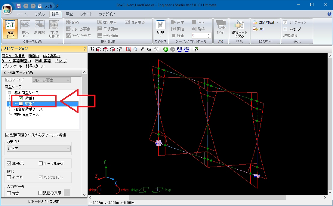
In the figure 5, bending moment of both of the "load case 1"
and "load case 2" are displayed. However, both operation of (1)
and (2) are performed. In other words, the "load case 1" is ticked,
and the "load case 2" is inverted. The bending moment of both
load cases are also displayed in this way. |
 |
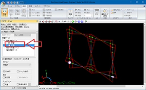 |
Fig. 4 Bending moment of the "load 1" and
the "load 2" (method (2)) |
Fig. 5 Bending moment of the "load 1" and the "load 2"
(method (1) + (2)) |
Tips
Switching of load cases becomes fast by selecting one load case (operation
(1)) and pressing [↑] or [↓] without ticking any load cases.
|