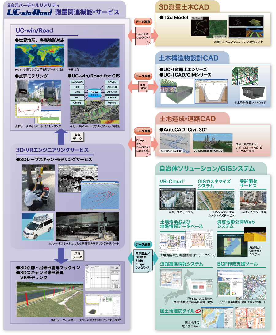
 UC-win/Road Drive Simulator UC-win/Road Drive Simulator
4 wheels vehicle drive simulator packaging system |
|
It allows you to create several driving situations and re-create it under
complete control. Recently Driving Simulator is widely used for vehicle
system development or interactio research among drivers vehicles, road
and traffic, on ITS traffic system research.
- Driving environment in 3D environtment can be freely created via UC-win/Road
- Standard plug-in included
- Standard VR data is free and scenario customization is supported
- Various environments can be reproduced via visual option tools
- Reasonable pricing mass OEM production
- Supports high simulation needs by customization
|
 |
|
|
Page Top  |
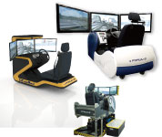
UC-win/Road Experience Simulator
6 axis motion unit/Subaru Driving Simulator |
|
| Based on Subaru automobile's technologies, the simulator body adopted 6
electric axis motion units (patented) developed by merging flight simulation
technologies from aerospace division of Fuji Heavy Industries and automobile
technologies from Subaru automobile.The use of actual car steering mechanism
gives you a sense of realism whilst driving.UC-win/Road Experience Simulator
allows you to simulate driving environments in accordance with the rapidly
improved car safety technology of ITS technologies (crash avoidance, decreased
impact, etc.) |
|
 |
|
|
| Page Top |
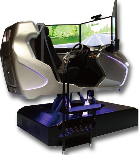
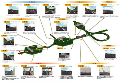
Highway Driving Simulator
Potential hazards on highway can be replayed by the driving simulator |
|
FORUM 8 has installed custom Highway Driving Simulator to Convention on
Social Contribution of Highway on March 1st, 2010. The simulator is already
used at several events and exhibitions on highway and its facility.
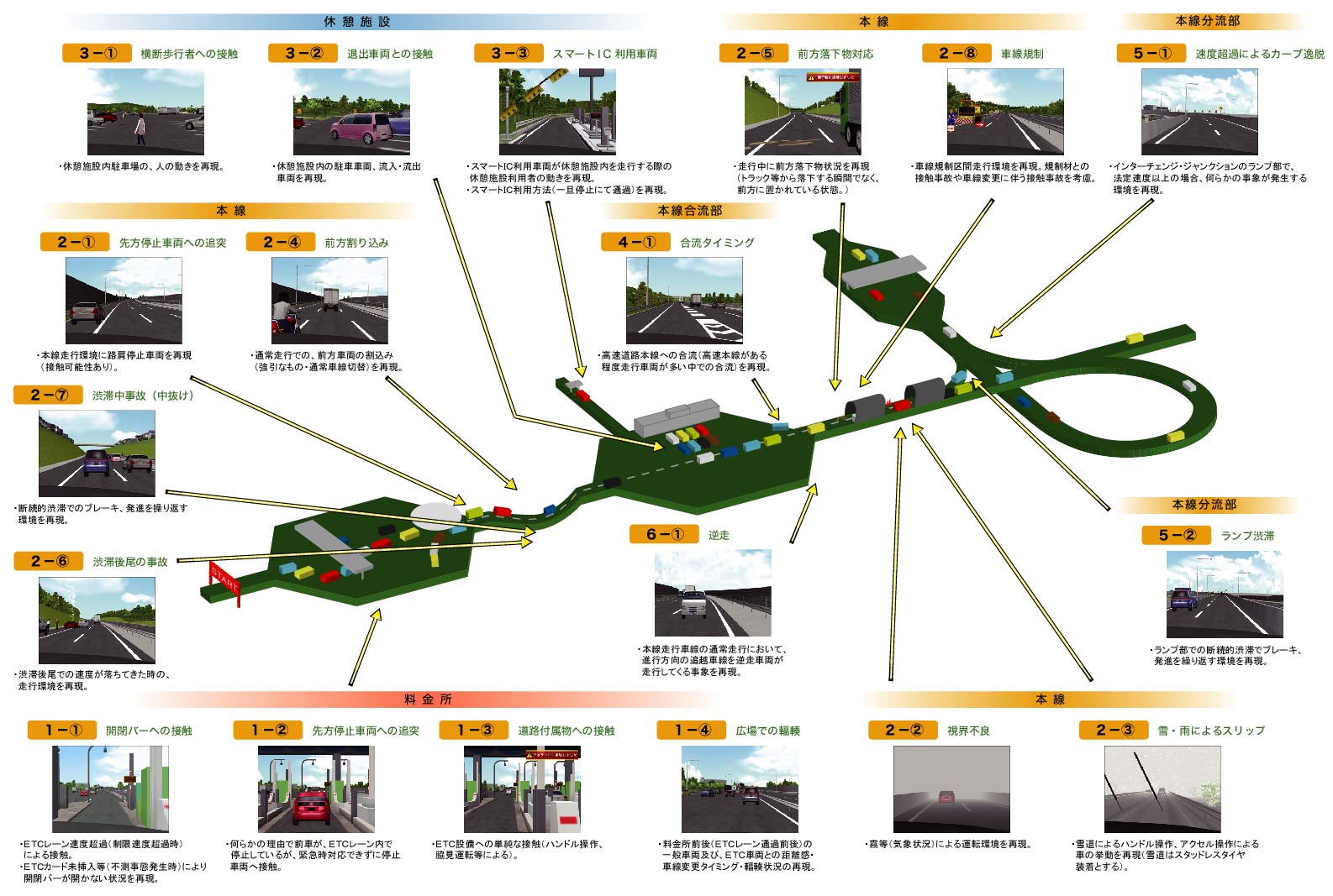
This simulator has been developed based on the award winning UC-win/Road 3D Virtual Reality software, with which drivers can experience potential hazards on highway. 3 scenario combined with 19 events can be set and the simulator outputs tabulated driving diagnosis according to the driving log.. The hardware of the simulator employs 6 DOF motion platform with real car parts option made by SUBARU.
- Experiencing 19 hazardous events on highways and its facilities
- Event items to set the experience driving
- Hardware : 6 axis motion units / Driving Simulator
|
 |
|
| Page Top |
UC-win/Road Safety Driving Simulator
Driving simulator for driving school according to certification standards for driving simulator(Uncertified) |
|
Based on the certification standards for driving simulators
|
1. Hazard perception 2. Night-time driving 3.
Sudden braking
4. Driving on the highway 5. Location-specific conditions
6. Driving in bad condition |
Optional scenarios
|
7. Identifying violations 8. Night-time visibility |
System configuration
|
- PC for central control - PCs for the driving simulators
- Printer
*All units are connected on a network |
Diagnosis / Data collection program
|
- Diagnosis software - Data collection software |
|
 |
|
| Page Top |
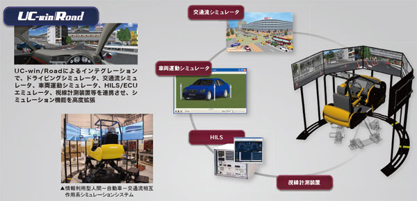
Human-Vehicle-Traffic Flow Interoperable Driving Simulation System for
Interactive Information Exchange
Driving simulator with 6 degrees of freedom 0.7G motion platform for highly
sophisticated research purposes |
|
FORUM8 delivered research-purpose driving
simulator referred to as "Human-Vehicle-Traffic Flow Interoperable Driving
Simulation System for Interactive Information Exchange" to Kyushu
University Graduate School of Integrated Frontier Sciences on March 22, 2012.
The driving simulator will become the driving force for educational research
activity on the next generation information / control devices in vehicles.
Research-purpose Driving Simulator has been delivered to Kyushu University.
This driving simulation system was realized by linking the driving simulator,
traffic flow simulator, vehicle dynamics simulator, H I L S/ E C U simulator,
and eye tracking system and integrating them all into UC-win/Road. On May
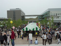
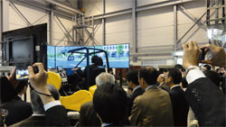
13, 2012, the driving simulator was exhibited to the public for the first
time since its delivery as one of the highlights of "Kyushu University
Festival" held on Ito campus to commemorate the university's 100th
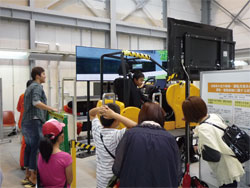
anniversary. 106 people, many of them families, lined up to test drive
the state-of-theart simulator.
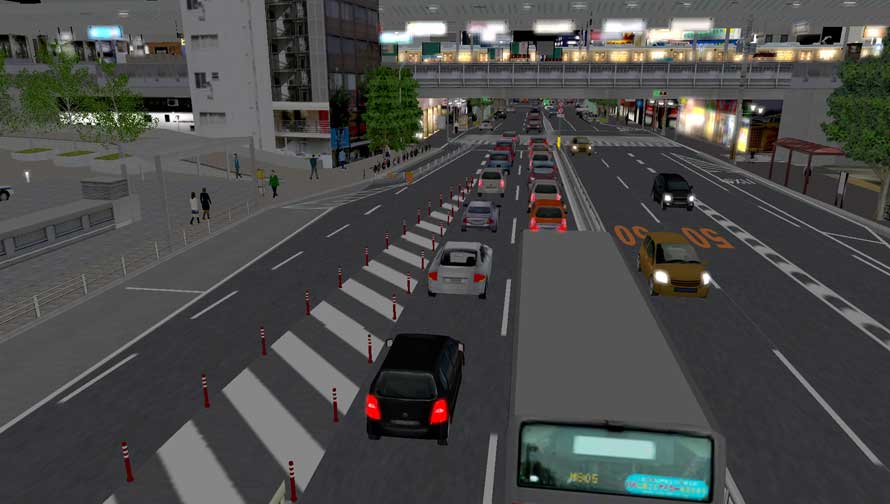
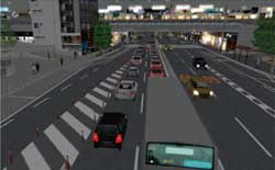
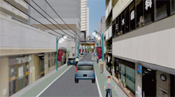
The virtual test course is a 2 minute run that starts from a point in Taihaku-doori
- a main street that runs across Fukuoka city - near FORUM8's Fukuoka Business
Office and ends at Hakata station. Test drivers got very excited during
the course of their drive as many of them acclaimed the driving simulator's
cutting-edge technology by giving comments like "I'm really impressed
with its ability to visualize so many aspects of the real world with high
degree of realism. The image I'm seeing on screen is very pretty."
FORUM8 delivered another research-oriented driving simulator (6DOF 5 Channel)
on March 2012 to Faculty of Engineering, Kyoto University Graduate School
of Engineering, Kyoto University.
 |
 |
 |
 |
unveiling ceremony of Human-Vehicle-Traffic Flow Interoperable Driving
Simulation System
for Interactive Information Exchange
(March 23, 2012 / venue : Kyushu University) |
|
|
|
| Page Top |
8DOF Traffic Safety Simulator |
|
|
This large scale Driving Simulator was planned and built for Rearch Institute
of Highway Ministry of Transport in China (hereafter, RIOH) to be used
for their traffic and safety research activity. RIOH outlined the specification
of the Driving Simulator. In January 2009, FORUM8 received the order of
the customized development of this Driving Simulator in the international
tendor on its own., and in February 2014, the Final Acceptance Test was
complete, marking the completion of the entire project. The following is
an explanation of the feautere and overview of the high performance large-scale
Driving Simulator based on Interactive 3D Virutal Reality Simulation &
Modeling Software UC-win/Road.
|
 |
|
|
| Page Top |
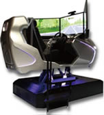
High Precision Driving Simulator for Vehicle Performance Analysis |
|
|
This simulator is the world-first 5-screen 3D stereoscopic VR driving simulator(*1)
that incorporates numerous elements such as driving simulation, traffic
simulation, and vehicle dynamics& performances, by building upon the
the interactive 3D VR software UC-win/Road.
FORUM8 has built and delivered this simulator inside the Nagoya University's National Innovation Complex (NIC) in June 2015.
>> Catalog of High Precision Driving Simulator for Vehicle Performance
Analysis (PDF in Japanese, 1649KB)
|
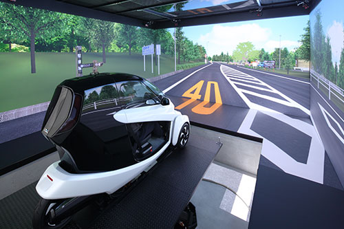 |
*1 As of June 2015, no large 5-screen CAVE simulator has been known to also include a real cockpit, hence this is currently a true "world-first" attempt. |
|
UC-win/Road Customization System
|
|
- VR Motion Seat
- Lily Car
- Super-jumbo DS system : 6 axis + Yaw/X table and the entire circumference
8 projection / cluster composition
- UC-win/Road Bicycle simulator
- UC-win/Road Wheelchair simulator
- UC-win/Road Train simulator
- UC-win/Road Train signal visibility system
- UC-win/Road Ship handling simulator
- Man-machine interface
Develop high quality customized system flexibly by subdividing modules
at low cost
<Easy to modify / add the module (driving simulation system)>
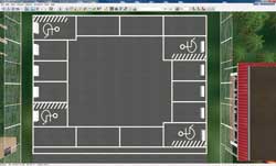
Here are the developments cases in which we changed UC-win/Road vehicle
dynamics model, customized user's hardware and log outputting of driving
condition. It calculates the vehicle's movement by inputting the operation
quantity of the pedal and the steering wheel from the usual game controler
as an existing module structure (excluding added part on the right chart).
Furthermore, it performs the calculation of vehicle's acceleration and
track by an independent module. We modified the existing module for "Calculation
of vehicle's acceleration". By doing so, customization of engine dynamic
model of vehicles is made possible. Also by the modification of module
for "Calculation of vehicle's track", we could fit the need of
the road surface and the tire's adherence model. By the addition of "analog
pedal device input" module and "pedal operation input switch"
module, we could ensure the coexistence of the game controler and the other
hardware, and accept the analog device. Finally, by adding module for "log
acquistion and log saving", you can now obtain and output information
regarding drive simulator.
The use of upgraded function and new feature function being developed in
VR-Studio®
<Development of a new module / using in advance a function of product
under development>
In case we want to achieve a new function by customization, we develop
the basic technique in a unique way, and continue on to design and develop
in a way that would provide the most of the what the new function of the
package has to offer.
A function that runs scenario which can make the driving simulation improve
significantly has been developed further by making use of know-how built
up through customization and it will loaded as a new function to the next
version.
By the scenario function, it can put event in motion, elicit response from
the drivers, and develop the stories of various driving. Also as for a
newest technology of computer raphics, we adopt Shaders language for the
next product, VR-Studio, and develop the texture processing of geography
and the advanced expression of source of light. Do to the fact that they
needed to be customoized, they are many of them that have been developed
from the basic technique to the unique technique. Also large scale model
developed in VR-studio and the customization development taking LOD function
in advance are vailable.
The fulfillment of advanced simulation by the cooperation with hardware
<UC-win/Road Drive Simulator / Motion Platform>
It is possible to customize UC-win/Road Drive Simulator(DS) which is a
representative of cooperation with hardware. "Motion platform"
is has a maximum of 6 degrees of freedom, Pitch, Roll, Yaw, Sway, Surge,
Heave, serving as a very realistic system that can provide maximum amount
of feel of driving.
Past developmental achievements in terms of DS include DS for car research,
development of safe system, training simulator, simulator for publication,
and train simulator. In the conbination with hardware, it can cover various
simulation needs because it doesn't only make use of the features of real-time
3D VR which is essencial in cooperation with software but also it's the
system which can perform the flexible drawing up of 3D space, modification
and controling scenario and event. |
|
| Page Top |
|
 |
|
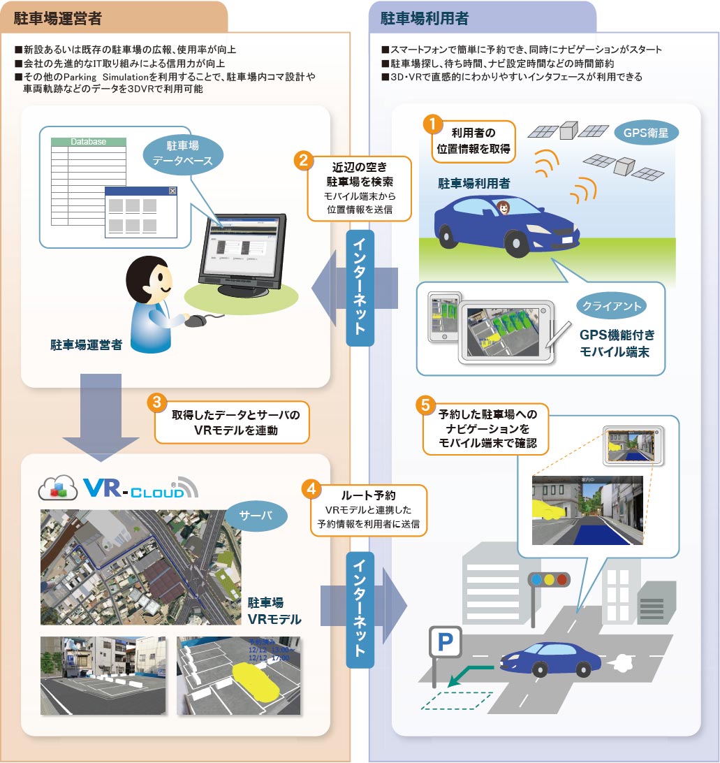
Parking Solution
|
With the cooperation between the vehicle trajectory / parking lot CAD and
UC-win/Road, we provide integrated solutions such as a searching and navigation
system for empty spaces in the parking lot by using VR-Cloud®, autonomatic
parking system by the synchronization with Robo Car® in addition to the
creation of the parking model and its 3D VR simulation made from the drawing
information. |
|
|
|
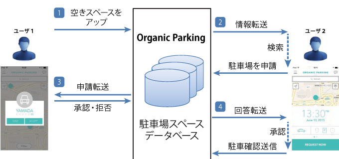
●Organic Parking
This system was developed by Organic Parking in the US, aiming at a more
eco friendly society with less congestions by reducing the time to seek
for the parking space.
This service is patented in the US and is internationally patent-pending.
FORUM8 has obtained the exclusive development right in Japan, and started
to customize it.
- Mobile application for searching and reserving parking lots on mobile phones
and tablets.
- Providers send information of parking lot or a place where to park a car,
and a person who wants to use the parking space reserves via the system.
- The reason why it is named as Organic is that it promotes the community
creation and the networking and cooperation between humans in addition
to the environmental aspect that it avoids congestions and traffic jams
and reduces emission.
- We are developing this service not only for reserving parking space but
for getting a spot at events like fireworks event and cherry blossom viewing.
- Basic function: Empty spaces are displayed on the map in real time. Paid
parking lot, parking space on streets, and vacant space in private property
are supported.
- Vacant information is updated by users. When drivers finish to use the
parking space, they connect to the service and send information of empty
space to pass it on to other users searching parking space.
|
|
Read a QR code or click
to the download page |
 |
|
|
Page Top |
|
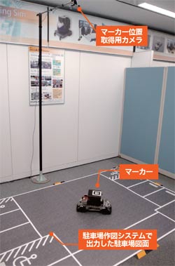
UC-win/Road Vehicle trajectory / Parking lot CAD Automatic parking system |
|
|
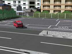
The vehicle trajectory drawing/ Parking design/ Automatic parking system
3DVR simulation is achieved by using the drawing information and by linking the creation of the trajectory mapping and the creation and design of the parking lot with UC-win/Road. In addition, an automatic parking system is available through the synchronizing of the VR model and RoboCar(R). |
|
- Vehicle trajectory drawing system
This allows the user to calculate and draw the trajectory of vehicles based on the figurative theories of "Style of right angle turning trajectory drawing of semi-trailer and full-trailer (JASO ZOO6-92), Society of automotive engineers of JAPAN, INC." etc.
Driving simulation on visualized routes and existing routes and drawing vehicle trajectory can be conducted efficiently.
- Parking drawing system
This is a CAD system which designs parking lots based on the parking standards with the figurative theories of "Standard Parking Regulations",
"Road Design Standards" etc. (Drawing plan view).
It allows the user to export the constructed parking drawing to CAD data which can be used in our "Vehicle Trajectory Mapping System".
- UC-win/Road RoboCar® Auto parking plugin
This system allow for the automatic operation of a steering wheel at the
time of parking based on the information from a camera or ultrasonic sensor
by linkage between UC-win/Road and RoboCar(R). Parking can be conducted
automatically by the driver simply pressing the button outside the car.
 |
 |
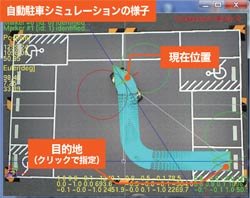 |
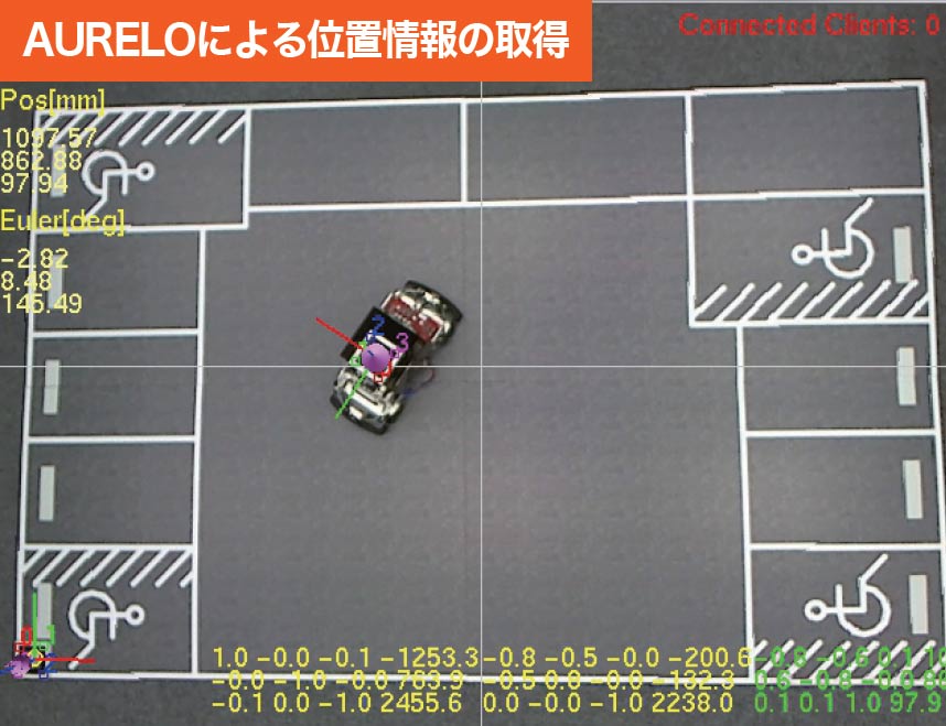
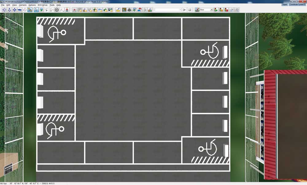
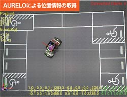
 Automatic parking simulation of RoboCar® by using AURELO Automatic parking simulation of RoboCar® by using AURELO |
 |
 |
Automatic parking can be checked
in UC-win/Road |
VR parking lot.
View from any camera position you like. |
|
|
|
Page Top |
|
 |
|
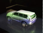
The most advanced solution technology using robots
|
●UC-win/Road for RoboCar®
Fusion of car robotics platform and virtual reality
With UC-win/Road, you can create a vast virtual reality environment in
a short time in easy workflow and operations. The linkage with RoboCar®
can be applied to simulators in the mixed reality in addition to in VR,
and it is expected to be used for a variety of simulators.
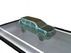
 What is RoboCar®? What is RoboCar®?
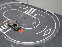
VR simulation system can be used to control 1/10 electric car scale model
on model road. This can be performed by integrating "UC-win/Road",
which is the virtual reality soft with well-developed driving simulation
function and "Robo car", which is the car robotics platform mounted
robot technology. This system allows users to create precision space images,
many different styles of traffic environment and scenarios by using virtual
space in VR, and experiment with them.
Linkage between UC-win/Road and RoboCar®
In UC-win/Road, you can set precise space rendering and a variety of traffic
environments and scenarios, and travel in the virtual space. RoboCar®
is a one-tenth scale model of the actual car and runs in the real space.
Combination of these characteristics enables the simulation in the mixed
reality, which is not possible in the virtual space. |
|
 |
|
 |
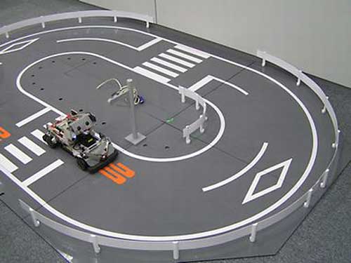
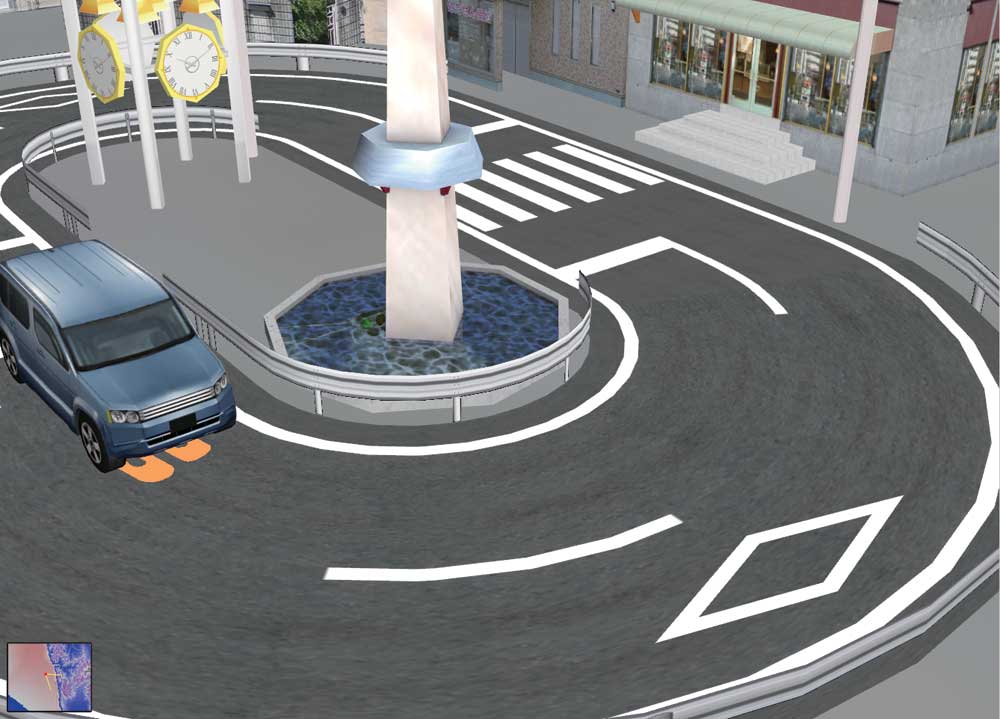
 Creating the driving environments (left) and running in VR space (right) Creating the driving environments (left) and running in VR space (right) |
|
| |
|
|
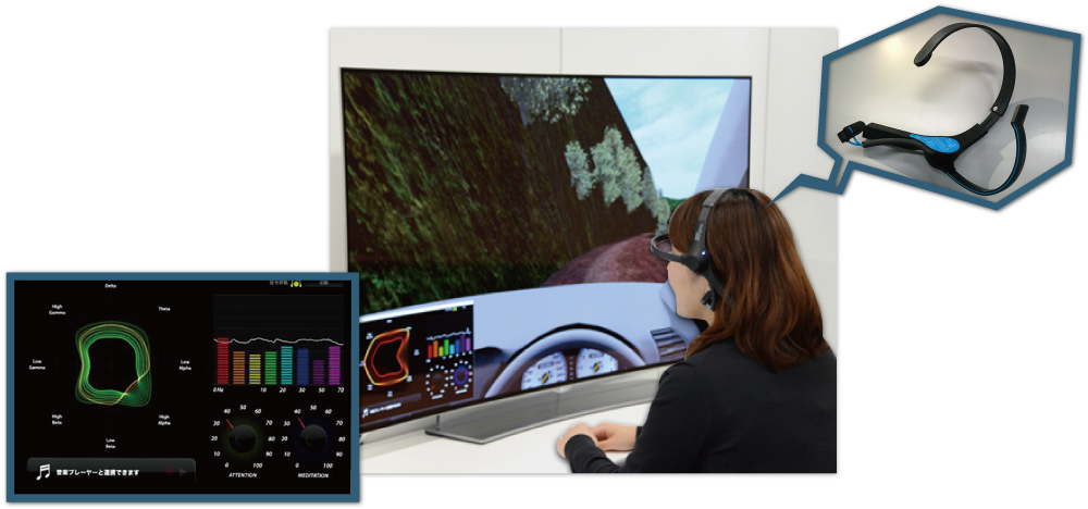
●Mind&VR UC-win/Road for MindWave Mobile
Drive simulation in UC-win/Road with the brain-measuring interface MindWave
Mobile
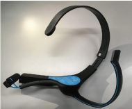
| MindWave Mobile developed by NeuroSky is a wireless stereo head device equipped with a brainwave sensor. It measures the brainwave of the wearing person that is sorted by differences of frequency like alpha and beta, and converts it to the psychological state such as degree of concentration and relax via the original algorithm. |
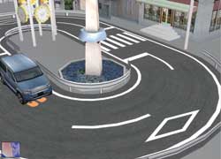
| By using MindWave Mobile plug-in and cooperating with VR data, users can
perform operations and simulations using the acquired data. In the drive
simulation below, speed of the vehicle is controlled according to the driver's
degree of concentration. If the driver concentrates by staring at a point
on the screen, the vehicle accelerates, and it decelerates if the driver
gets distracted. |
 |
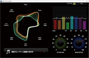 |
 MindWave Mobile (Neurosky) MindWave Mobile (Neurosky) |
"Brainwave visualizer" (Neurosky) |
■Case of use
Mindwave driving UC-win/Road MindWave Mobile plug-in
Driving by brainwave is possible when you start the drive simulation with
MindWave Mobile wearing.
Acceleration and brake can be controlled by brainwave.
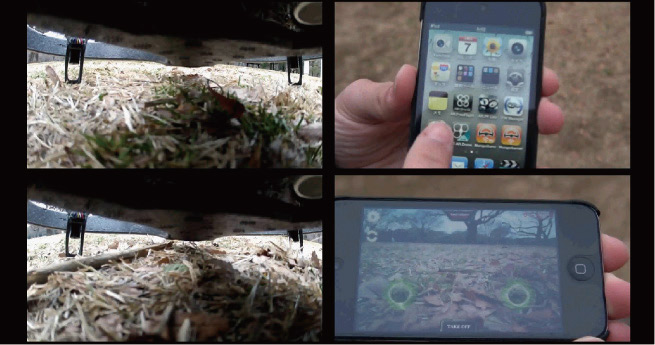
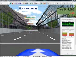
F1 race
Formula One (F1) racing is one of the study cases of EEG technology use.
We loaded two MindSet units in real-time (@60Hz) and developed the interface
that can extruct the meditation coefficient and the attention coefficient.
 |
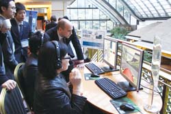 |
| ▲Phoenix F1 circuit |
▲Appreciated as the system on display
because of its game element |
|
|
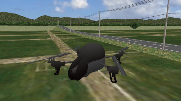
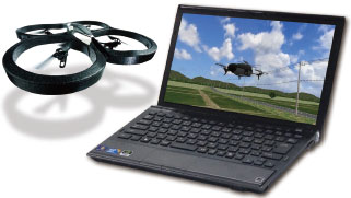
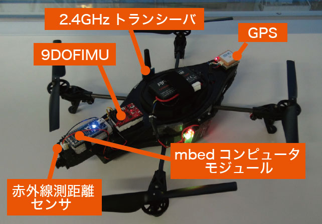
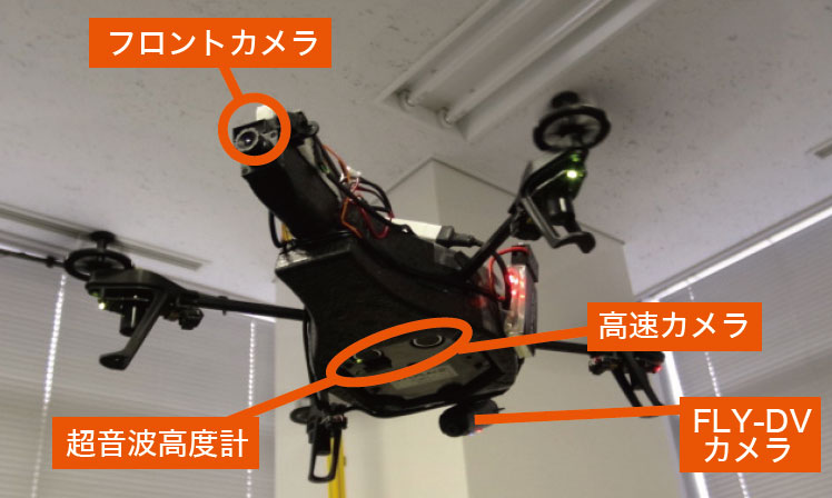
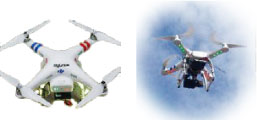
●Autonomous flight UAV
Autonomous flight monitoring system
■Operation by mouse or keyboard. Wireless data communication via Wi-Fi.
■The computer in the UAV automatically controls the balance and easily enables the advanced movement of the UAV such as up and down, forward and backward, and left and right.
■Images can be monitored through a front camera or high-speed camera and recorded with FLY-DV camera in detail.
■Measures the position of AR.Drone by GPS
■9DOF IMU (Inertial Measurement Unit) measures the acceleration, gyro, and earth magnetism, and confirms the direction of AR.Drone.
■It avoids the collision by using the infrared distance measuring sensor.
 |
 |
 |
|
▲AGUL customization |
▲AGUL test flight |
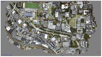
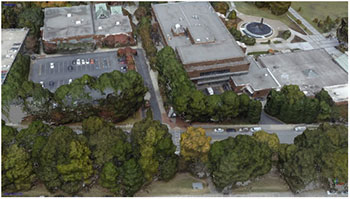
Micro Aerial Pilotless Scanning System (MAPs)
| Mapping of a large area through the use of a pilotless unmanned aerial
vehicle (Drone). |
 |
 |
 |
 |
 |
 |
 |
| ▲Customized autonomous flying robot |
▲Linking 3DVR and autonomous flying robot |
|
|
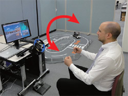
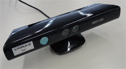
●Kinect™ Driving Simulator
Handless driving simulation by infrared depth sensor
This system allows you to operate driving within UC-win/Road by the movement
of both hands like operating the steering wheel in front of the Kinect™.
The position information of the both hands of a driver detected by the Kinect™ is converted to steering wheen, acceleration and brake of a car.
Imaging of vehicle control and driving operation by the infrared depth sensor
 |
|
 |
| ▲Steering operation (right-turning / left-turning) |
 |
|
 |
| ▲Acceleration operation |
|
▲Brake operation |
|
|
●Technologies used for UC-win/Road Air Driving
Fine and precise driving operation without control devices
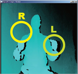
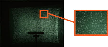
Recognition of skeleton
It extracts the same object from the distance information detected by the
infrared depth sensor and identifies human characteristics. When the object
person takes a specific pose, it does a calibration and recognizes the
skeleton structure. |
|
 |
|
 |
| ▲Kinect(TM) sensor |
▲Pattern of the infrared laser |
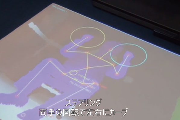
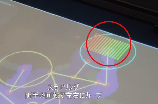
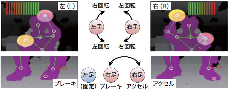
Detection of steering angle and steering direction
The right and left direction of the steering wheel and its steering angle are detected as an analog value from the positional relationship betweeen the user's right and left fist. How much the steering wheel is turned is indicated by a row of bars that change color from green to red. The bigger the steering angle, the more red the bar will be.
|
|
 |
|
 |
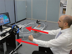
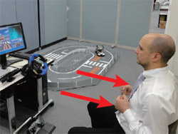
Distingishing accelerator from brake
Accelerator
This is detected as an analog value from the amount of pressure the driver exerts on the accelerator pedal. |
▲Travel in a straight line |
▲Right turn: As you steer to
the right, the red bars will
increase in the right direction. |
●Acceleration: The stack of bars will increase in the upward direction.
●Brake: The stack of bars will increase in the downward direction. |
|
|
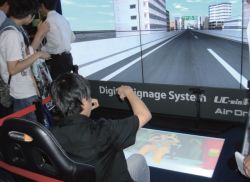
●Multi-Cluster Digital Signage System with infrared depth sensor
The interactive digital signage system uses a 6K display on multi screens as well as the infrared depth sensor.
This system can be interactively operated using the function of gesture interface and motion capture. Xtion PRO is used for the infrared depth sensor. The signage is operated interactively compared to the previous digital display. We also provide this service and various products such as real time VR simulation using the multi cluster system and UC-win/Road, CG rendering using the high-performance computer etc.
 |
 |
▲6K Digital Signage AirDriving
(TOKYO GAME SHOW 2011) |
▲AirDriving interface |
High-definition movie files generated by POV-Ray is a feature of FORUM8'
"High-performance computing on cloud services® CG movie service".
The high-definition movie file can be provided by use of a supercomputer.
Since the movie files are generated by POV-Ray, their script files can
be edited using an editor etc. after the movie files are exported to UC-win/Road. |
|
|
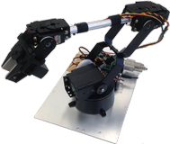
●UC-win/Road for Robot arm
Robot arms in virtual space and in real space move in conjunction with
each other. |
 |
|
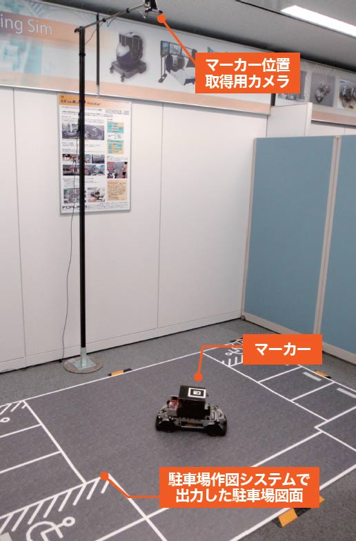
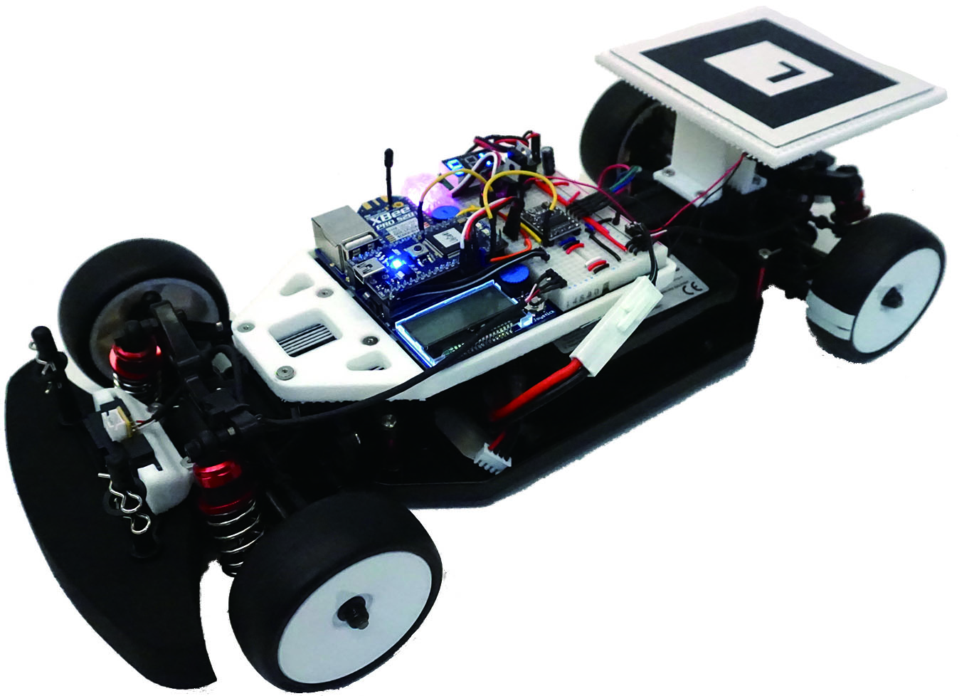
●Lily Car
Autonomous car system via a scale model robotic car linked with VR
The Lily Car is a scale model robotic car, which purpose is to emulate
on a small scale the behavior of actual cars and help the development of
robotic cars.
The cars run autonomously on a test course, with several predefined paths.
At any time, the user can switch the control mode between the manual or
autonomous mode. The PC control interface connects to the Aurelo system
to get the position and orientation of each car and sends the proper commands
to the cars to make them follow the selected path.
System configration of Lily Car
- Chassis of a 1/10 RC car - Driving motor - Steering motor
- Infrared distance sensors for collision detection
- An AR marker for the car tracking
- A wireless module to allow communication and control from a remote PC
- A main controller to manage the whole system |
|
 |
|
|
|
Page Top |
 |
●MR : Mixed Reality ●AR : Augmented Reality
Shibuya cloud model and interactive device
Development of Linking System for VR and Interactive Devices
|
|
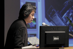 |
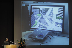
Mr. Taro Narahara
(Graduate School in Harvard University, USA)
|
|
Mr. Narahara mentioned a project in which he introduced actions captured from real people into motions of figures, and represented more realistic figures on UC-win/Road.
In addition, he explained the mechanism that enabled real-time interaction by linking simulation and UC-win/Road on a real time basis through joint development of plug-ins with FORUM8. |
|
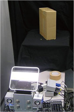
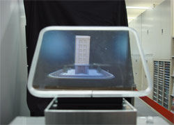
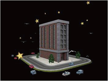
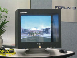
| 3D Stereo System Naked eye 3D Stereo System |
An example of system configuration
Glassess 3-dimensional image. Composition of a diorama and 3-dimensional image is displayed.
What is 3D-B-Vision?
The 3D-B-Vision is a Mixed Reality, or more specifically, an Augmented
Reality (AR) hardware system. AR is becoming more popular because of its
function in projecting digital information over the real (physical) world.
And with 3D-B-Vision, there is the added benefit of being able to project
the digital information in the form of 3D-Stereoscopic CGI. The information
can be displayed over architectural models or other physical objects.This
glassless system is achieved by the use of two small projectors, placed
eye-distance apart (for the 3D stereo capabilities). The participant looks
through a transparent view window towards the physical object, and with
the use of an overhead silver screen and lens filters, the 3D stereo image
can be seen along with the physical setup. With UC-win/Road version 4,
real-time simulation information can be projected. UC-win/Road 4 will include
a 3D Stereo plug-in that can take full advantage of the capabilities of
3D-B-Vision. Cars, Pedestrians, and other moving elements can be shown
acting together for an effective presentation with the 3D-B-Vision's stereoscopic
projection.
 |
 |
|
Normal view via 3D stereo |
Benefits
- With UC-win/Road, real-time simulation information can be used with 3D
Stereo.
- Does not require polarized glasses. Depending on physical model size,
many can be used as 'kiosks' with varying information strong visual impact
with moving data.
Developed by: Ishikawa Kougaku Zoukei Laboratory Co.,Ltd. (http://www.holoart.co.jp/)
|
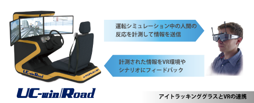
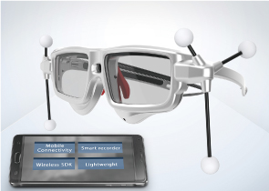
UC-win/Road Eye tracking system  |
Wearable device that measures information of humans line of sight and acquire
its data.
Possible to connect to the drive simulation in VR space of UC-win/Road.
* Separate customization is required.
Eye Tracking Glasses Option
Eye tracking glasses that can "visualize" humans line of sight
 |
|
| Sampling rate |
60Hz or 30Hz |
| Calibration |
0, 1, 3 points |
| Recording microphone |
Yes |
| Scene camera (definition) |
1280x960p @24 fps
960x720p @30 fps |
| Recording angle of the scene camera |
Horizontal: 80 degree
Vertical: 60 degree |
Continuous
recording time |
(PC) |
2 hours |
| (Galaxy) |
2 hours |
Recording
Capacity |
(PC) |
18 hours |
| (Galaxy) |
20 hours |
| Weight (Glasses main unit) |
47g |
| Weight (Galaxy) |
176g |
| Size (Glasses main unit) |
135 x 69 x 23 mm |
| Precision of regard |
0.5 degree |
|
Contents construction
- 60Hz binocular Eye Tracking Glasses with HD scene camera
- Snap on frame for ETG (3D)
- Row dataful access SDK
- Recording software Recording iView license
- VRPN Server |
|
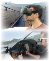
Eye Tracking HMD based on HTC Vive Option
Made by SMI and based on HTC Vive. Line of sight information is attached
to the high-performance model of 250 Hz.
 |
|
Eye tracking
| Tracking |
250Hz (Both eyes) |
| Tracking range |
Full visual field
(110 degree) |
| Precision of regard |
0.2 degree |
| Calibration |
1, 3, 5 point |
Measuring data of
Interpupillary distance (IPD) |
Point of regard on display (left, right, both eyes), Standard point of
regard, gaze tracking |
Headgear
| Hardware |
Plug and play connection of HTC Vive headset / Unecessary to adjust before
connection / USB |
| Head unit |
Eye tracking
Module part: 55g |
Operation device
| System requirement |
PC with HTC Vive activated |
| OS |
Windows10 64bit |
|
Contents construction
- HTC Vive main unit / attachment
- Binocular Eye Tracking at 250 Hz (Embedded module)
- Row data full access SDK
- Plug-in for Unity, WorldViz Vizard, Unreal Engine
- Recording software iView license
- VRPN Server |
|
* The specification above may be altered without notification for improvement.
Developed by SMI https://www.smivision.com/ |
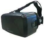
| HMD System Head Mounted Display System |
3D image output by Oculus Rift With extremely wide view angle. Head tracking by the internal sensor.
■What is Oculus Rift?
A Head Mounted Display (HMD) developed and provided by Oculus VR in the
US at lower price than existing HMD. Head tracking by the internal sensor
and 3D image output of wide view angle are available.
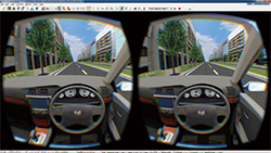
■Display
Oculus Rift has an overwhelming wide field of view as a HMD. This is because
that the fish-eye model screen shows wearers the flat liquid crystal display
as if he/she is looking at a semi-hemisphere projector screen in front
of him/her. Combination with stereoscopic view due to the difference of
view between right and left improves the immersion feeling into the VR
space. In addition, existing HMDs display normal images owing to spending
much cost to the optical system in order to reduce the lens distortion
to the minimum, whereas the Oculus Rift renders source images so that wearers
can see good images when seeing through the distorted lens. |
|
 |
|
 |
| Oculus Rift DK2 |
|
Stereo view |
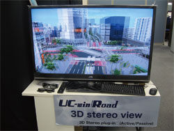
■UC-win/Road Oculus Plugin
Oculus Rift Plug-in creates a stereoscopic 3D image with lens barrel distortion and tracks the camera view within UC-win/Road in line with the user's head movement using the sensor data. |
|
| Page Top |

Simulation / presentation system in combination with physical model and
VR |
|
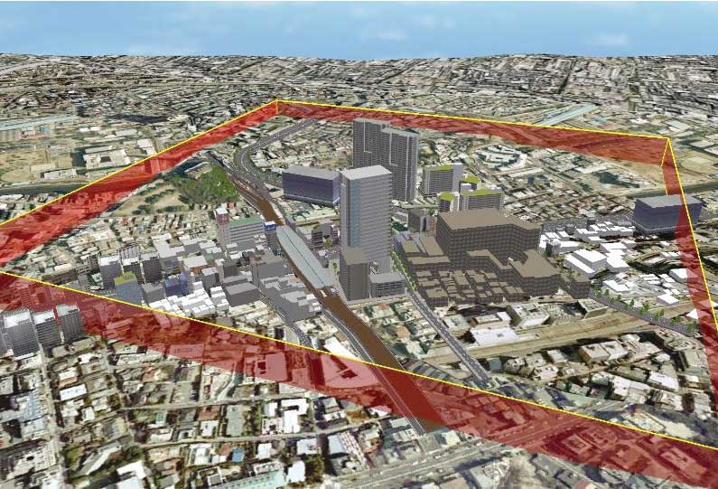
"UC-win/Road Physical Model and VR System" was developed based on the idea and cooperation of Associate Professor Tomohiro Fukuda of Osaka University, a member of W16. Thanks to the technology of providing a combined operation environment of physical model and VR system, it is a new type simulation/presentation tool combing the features of both environments. The system allows you to present information effectively and efficiently to the people concerned with different background and varying knowledge levels.
UC-win/Road Physical Model and VR System (Up&Coming '11 Early Spring Issue)
Technical Support : Associate Professor Tomohiro Fukuda,
Graduate School of Engineering, Osaka Univeristy |
Tool for examination with advantages of both physical and VR model
Advantage of VR : VR is highly flexible and expressive, and allows various considerations
such as reproduction of traffic flow or changed weather conditions, which
is impossible through a physical model.
Advantage of physical model : Physical model is more intuitive way to understand the overview of planning
including the distance and size. Physical model allows various people to
examine from the arbitrary viewpoints at the same time, understanding the
whole city model simultaneously and touching the model directly.
Deciding the viewpoint under consideration in a physical model and displaying
it in a VR model
The planning can be studied by easy and intuitive operation in comparison
with VR only. In "UC-win/Road Physical Model and VR System",
you can move in the VR space and make changes in the view direction by
indicating the view points to examine with laser pointer on the model.
The system consists of model, web camera, laser pointer, VR software "UC-win/Road",
and display unit to view the VR display space. As a whole, the system consists
of two functions: detecting laser pointer operation, passing detected information
to UC-win/Road and representing it in VR space.
Physical model VR system "Nakameguro Safety and Security Map"
exhibited in the Showroom
The physical model VR system of "Nakameguro Safety and Security map"
is exhibited in the showroom of FORUM8 Tokyo head office. Please come and
visit us.
Proposal and quotation of system
FORUM8 will offer the proposal and quotation of "UC-win/Road support system" based on the requirements of each customer. With UC-win/Road Support system, 3D VR simulation data can be created based on their needs. The created VR data can be modeled by exporting VR data to the physical model using 3D printer in a short time with "3D physical model service" so that the physical modeled VR system can be effectively structured. Since the created data can be produced as a 3D physical model by "3D modeling service", customers can create Physical Model and VR System effectively.
| Quotation example: "Nakameguro Safety and Security Map"
Physical model VR system |
The proposal system with the physical model in Nakameguro where FORUM8 is located. The maintenance condition of infrastructure in the basement and the inside space of building can be checked as "Area safety and security map" where the physical model and VR are integrated, and it can be used for the consensus formation in the city re-development project.
VR data creation : About 3,200,000 Yen
3D physical model creation : About 3,800,000 Yen
* Including the cost of ARToolKit license, Web camera, laser pointer, desktop
computer, 42inch display, UC-win/Road Ver.5 Advanced x1 license, customization
charge of UC-win/Road, and technical fee
Total 12,900,000 Yen
 |
 |
 |
 "Nakameguro safety "Nakameguro safety
and security map"
Overview of VR model |
The area in front of
Nakameguro station |
Meguro Ginza
Shopping Avenue |
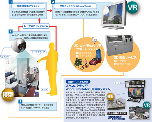 |
| System configuration |
|
|
|
| Page Top |
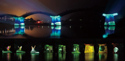
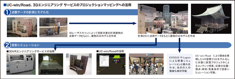
3D Projection Mapping
The practice of projection an image on a physical structure using 3DVR technology and contents |
|
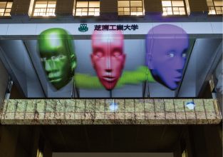
FORUM8 offers the state-of-the-art spatial visualization technology that
uses 3DVR data and image, namely the "3D Projection Mapping".
 |
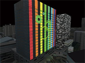 |
Projection mapping at Shibaura
Institute of Technology (2015.09.10) |
VR data to check image of projection mapping |
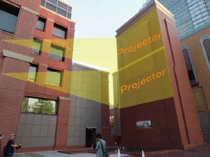
| Projection solution that uses VR |
By running a projection simulation via UC-win/Road and 3D Engineering Service, image can be confirmed by either lookign at the VR model or by exporting the model to a physical miniature model prior to the actual event.
The solution is an ideal tool for verification of contents, discussion with stakeholders, explanation and advertising to the customer, and of course advertisements before and after the projection event.
| An example of model projection plan |
An example of a plan
- Location : A relatively dark place outdoor and relatively easy to install and do projection mapping without affect traffic.
- Target structure : A tower shaped building with simple geometry
- Building size : W10m x D6m x H20m
- Building's material : Bricks (brown / opaque)
- Number of location from which image shall be projected : 2 at most.
- Projection distance : approx. 15m (A:near) approx. 40m (B:far)
Image of 10,000/20,000 lumen Projection plan via projector
10,000lumen has less brightness and area compared to 20,000 lumen. 20,000 lumen is usually recommended.
 |
|
| 2 projectors used |
List of model projection plans (2D, 3D contents)
*Cost of sound effects : The cost of devices that generate sound effects and the contents of sound effects, a total of approximately US$10,000 is included.
*Includes 3D animation content and sound effects
| Equipments |
1 projector |
2 projectors |
| Projector projecting a 10,000 lumen image |
US$ 65,000 |
US$ 100,000 |
| Projector projecting a 20,000 lumen image |
US$ 75,000 |
US$ 90,000 |
- Work is approx. 3 min. long and includes image and sound effects (user
defined, MA)
- Rental period of device generating image and sound effect : 3 days (1 day for preparation, 2 days at the event)
- Includes onsite testing and progress management
- Operator and image / sound effect engineer available
- Transport / travel / accommodation fee required for areas other than the Kanto region (Tokyo and the surrounding prefectures)
- Cost of stand and crane rental not included.
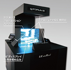
- A stereoscopic display device exceeding a hologram and enhancing mapping
around a 3D model. <Press release issued on March 30, 2016 (Japanese)>
- Projection mapping table <Up&Coming No.108 '15 New Year issue (Japanese)>
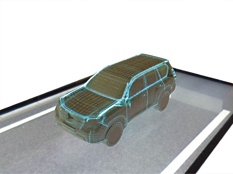
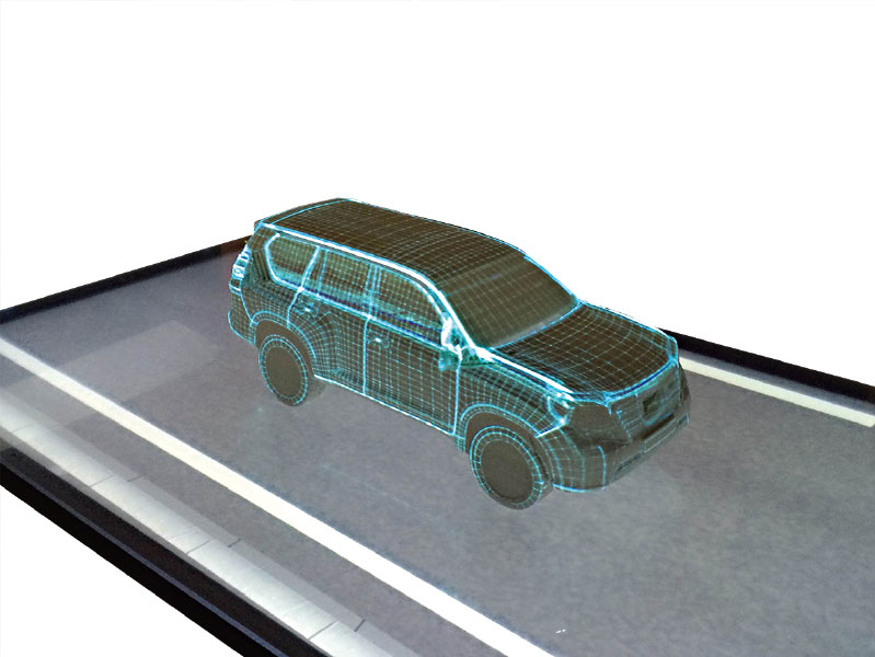
Design simulation system by all around mapping using UC-win/Road and a
3D model
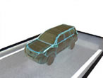
Ex: Projection of grid texture and real car texture
 |
 |
 |
 |
|
| Grid texture |
Real car texture |
|
|
|
Page Top
|
IM & VR |
|
Integrated Solution via BIM/CIM&VR
BIM / CIM is a model that integrates various information in building and
civil engineering, and a method of creating, managing and utilizing such
information. It is capable of designing and representing various information
within the entire life cycle of a building including basic and detailed
drawing, rendering image, presentation image, bill of quantities, etc.
As for VR and UC-win/Road, we offer "IM & VR solution" in
cooperation with simulations such as landscape, sunshine, traffic, wind,
noise, immersion / tsunami, evacuation, energy analysis, and construction
plan in front loading (consensus formation and planning). |
|
 |
|
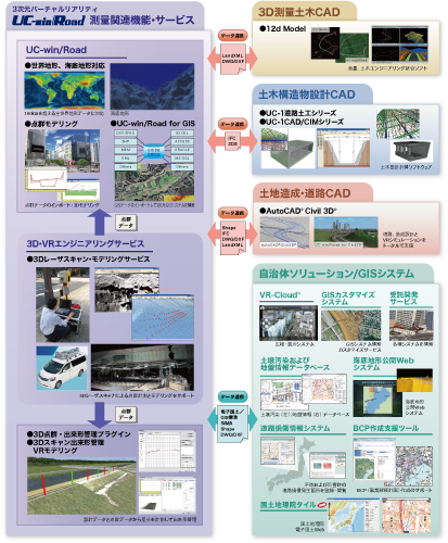
Surveying Solution
Integrated solutions that involve GIS / 3D Laser scanning / 3D Survey &
Civil Engineering CAD |
|
We offer integrated surveying solutions such as point cloud measurement
by 3D laser scanner and VR modeling of point cloud data via UC-win/Road;
data exchange between 3D survey CAD and civil infrastructure design CAD,
and VR system; and building a system that links GIS to VR technology.
 |
|
| Page Top |
|
|
|